
Method and apparatus for heat removal from electric motor winding end-turns

a technology electric motors, applied in the direction of windings, cooling/ventilation arrangements, transportation and packaging, etc., can solve the problem of reducing the cooling of winding end turns

Inactive Publication Date: 2009-06-09
GM GLOBAL TECH OPERATIONS LLC
View PDF8 Cites 67 Cited by
  • Summary
  • Abstract
  • Description
  • Claims
  • Application Information

AI Technical Summary

Benefits of technology

The present invention relates to an electric motor with a cooling system. The cooling system includes a plurality of cooling tubes that are connected to the winding end-turns of the motor. The cooling tubes absorb heat from the motor to improve its efficiency. The invention also includes a cooling tube with a thin wall thickness of about five percent of its inner diameter. The technical effects of the invention include improved cooling efficiency, reduced motor temperature, and improved motor performance.

Problems solved by technology

The thermal path from the winding end-turns through portions of the stator core to the liquid jacket typically includes many materials with low thermal conductivity, which can reduce cooling to the winding end-turns.

Method used


Image

  • Method and apparatus for heat removal from electric motor winding end-turns
  • Method and apparatus for heat removal from electric motor winding end-turns
  • Method and apparatus for heat removal from electric motor winding end-turns

Examples


Embodiment Construction

[0017]The following description of the various embodiments is merely exemplary in nature and is in no way intended to limit the invention, its application or uses.

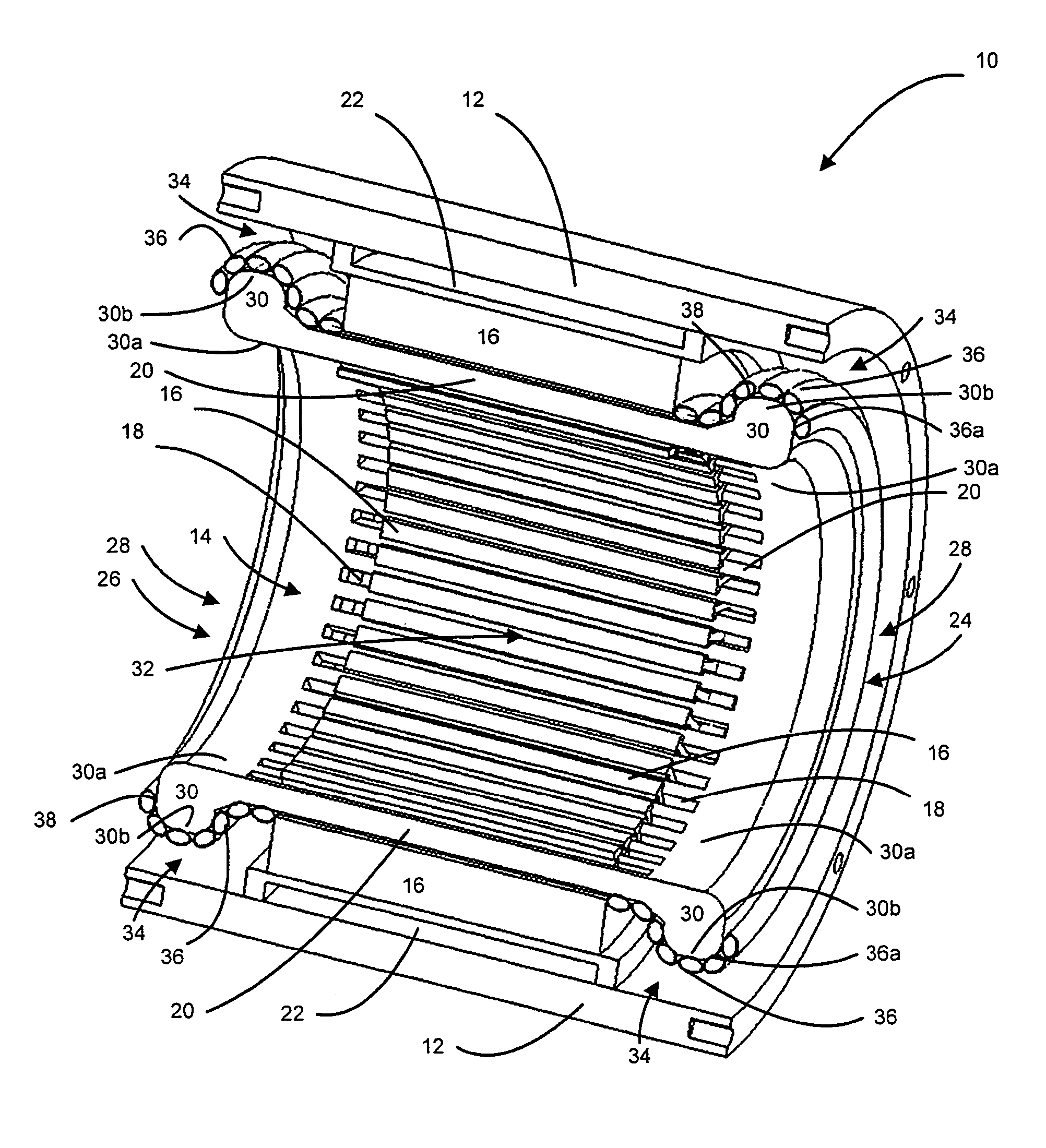
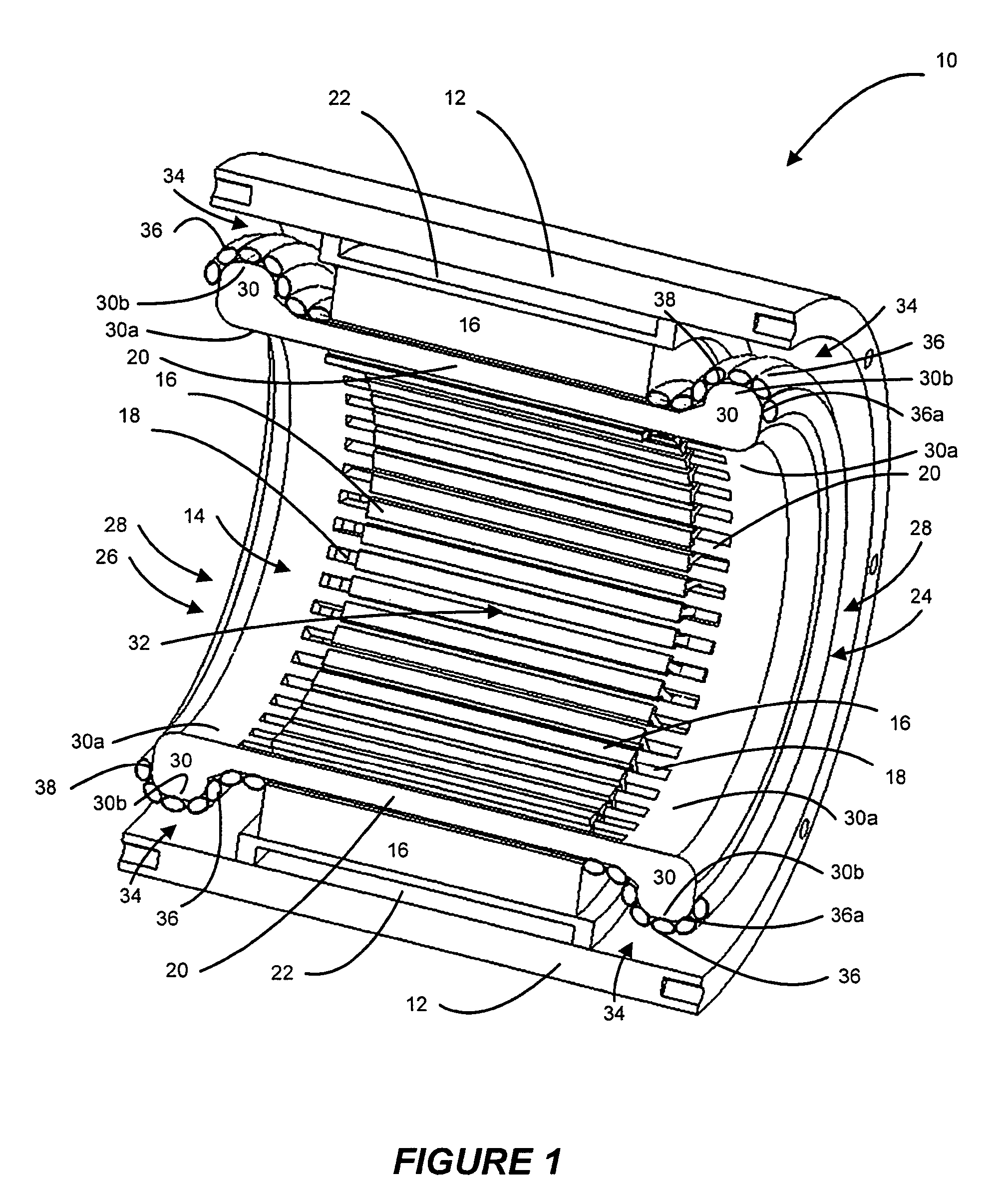
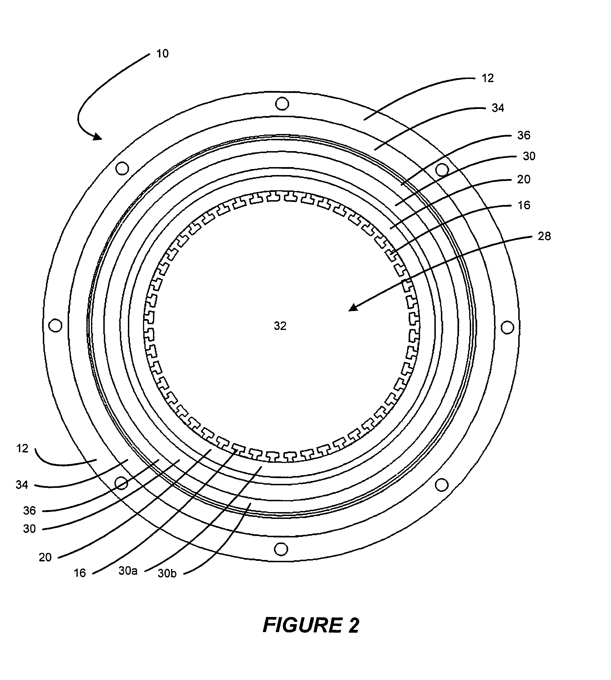
[0018]With reference to FIGS. 1 and 2, portions of an exemplary electric motor 10 are shown. The electric motor 10 includes a housing 12. The housing 12 contains the stator core 14. A stator core 14 can include a plurality of stator laminations 16 and a plurality of stator slots 18 formed within the stator laminations 16 in a manner known in the art. A plurality of electrically conductive wire windings 20 can be wound in and through the stator slots 18. A cooling jacket 22 can be disposed between the housing 12 and the stator core 14.

[0019]The wire windings 20 can be placed in the stator slots 18 and travel back and forth longitudinally between an opening face 24 and an opposed face 26, which can be collectively referred to as end faces 28. Winding end-turns 30 are formed as the wire windings 20 exit at the end faces 28 an...


PUM


Abstract

An electric motor includes a stator having a plurality of slots. The slots have slot ends and channels formed between the slot ends. A plurality of wire windings is disposed in the slots. A plurality of winding end-turns is formed by the wire windings and is adjacent to the slot ends. The electric motor also includes a cooling tube connected to a periphery formed by the winding end-turns. The cooling tube is operable to absorb heat from the electric motor. The cooling tube can cool the winding end-turns more efficiently than traditional electric motor water jackets and / or cooling fans.

Description

FIELD OF THE INVENTION[0001]The present invention relates to an electric motor and more particularly relates to liquid cooling of winding end-turns in the electric motor.BACKGROUND OF THE INVENTION[0002]An electric motor is typically either air cooled or liquid cooled. An air cooled electric motor will typically have air blown over a stator core and wire windings. In this arrangement, the electric motor can be referred to as a non-sealed or open motor such that air is able to blow through the stator core and over the windings. In a closed or sealed motor, air is typically blown across cooling fins on an exterior case of the motor to dissipate waste heat from the motor. In either the non-sealed or the sealed motor, air-cooling provides less complex but relatively inefficient cooling of the electric motor as compared to liquid cooling.[0003]A liquid-cooled electric motor typically has an annular jacket positioned between an outside diameter of the stator core and an inside diameter of...

Claims


Application Information

Patent Timeline
Patent Type & Authority Patents(United States)
IPC IPC(8): H02K9/00
CPCH02K3/24H02K9/19H02K9/22B60L2200/00Y02T10/64H02K9/227H02K9/197
Inventor WARD, TERENCE G.
Owner GM GLOBAL TECH OPERATIONS LLC
Learn More