Engine cooling water jacket

A cooling water jacket and engine technology, which is applied to the cooling of engines, engine components, machines/engines, etc., can solve the problems of poor uniformity of coolant flow rate, complex cooling system structure, and not widely used, and achieve uniform flow rate and reduced The effect of fuel consumption and tension reduction

Inactive Publication Date: 2011-05-04
CHERY AUTOMOBILE CO LTD
View PDF5 Cites 38 Cited by
  • Summary
  • Abstract
  • Description
  • Claims
  • Application Information

AI Technical Summary

Problems solved by technology

[0003] In the second form of cooling system, the common design of the water jacket of the engine body is that the coolant is pumped into the water jacket of the cylinder block by the water pump, and then enters the water jacket of the cylinder head through the cylinder gasket, and then flows from the water jacket of the cylinder head. This water jacket has a simple structure and simple control, but the flow rate uniformity of the coolant in the water jacket is poor, and the cooling efficiency is low
With the development of technology, a double thermostat control system appeared again. The coolant is pumped into the water jackets of the cylinder block and the cylinder head respectively by the water pump, and then flows out from the outlets of the water jackets of the cylinder block and the cylinder head respectively, through their respective The thermostat controls the large and small circulation. This circulation system can obviously improve the inhomogeneity of the flow rate of the coolant in the water jacket and improve the cooling efficiency. However, the cooling system has a complex structure and high manufacturing cost, so it is not widely used at present. widely

Method used


Image

  • Engine cooling water jacket
  • Engine cooling water jacket
  • Engine cooling water jacket

Examples


Embodiment Construction

[0024] The present invention will be described in detail below in conjunction with specific embodiments and accompanying drawings.

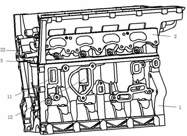
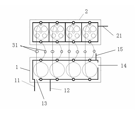
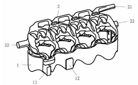
[0025] Such as figure 1 , 2 , 3, 6, the engine cooling water jacket of the present invention comprises a cylinder block water jacket 1 and a cylinder head water jacket 2, and the cylinder block water jacket 1 is separated by two baffles 13 and 14 to form a first flow passage 11 and a second flow passage The first flow channel 11 is connected to the water inlet 13 and flows through the exhaust side, the second flow channel 12 is connected to the water outlet 14 and flows through the intake side, the first flow channel 11 passes through the water hole 312 on the cylinder gasket 3 and the cylinder The cover water jacket 2 is connected, and the second flow channel 12 is connected with the cylinder head water jacket 2 through the water hole 311 on the cylinder head gasket 3 . Outlet 15 is the outlet of the cylinder block water jacket 1 leading to ot...


PUM


Abstract

The invention provides an engine cooling water jacket which has the advantages of simple structure, small volume, uniform flow rate and low pressure loss. The engine cooling water jacket comprises a cylinder body water jacket and a cylinder cover water jacket, wherein the cylinder body water jacket is separated by two baffle plates to form a first flow channel and a second flow channel, and the first flow channel and the second flow channel are communicated with the cylinder cover water jacket through water holes in a cylinder gasket; and coolant mainly flows into the first flow channel from a water inlet and flows through an air exhaust side, then flows into the cylinder cover water jacket through the water holes at one side of the cylinder gasket, subsequently flows into the second flow channel through the water holes at the other side of the cylinder gasket and flows through an air admission side, and finally flows out from a water outlet. Thus, the invention enables the flow rate of the coolant in the whole engine cooling water jacket to be more uniform, reduces the thermal-state deformation of the cylinder holes and improves the dynamic performance of the engine; and the water holes in the cylinder gasket can be arranged as required without being influenced by the design of traditional water jacket cylinder holes, thereby integrally increasing the flow areas of the water holes in the cylinder gasket, reducing the pressure loss of the whole water jacket and lowering the performance requirements for water pumps.

Description

technical field [0001] The invention relates to the technical field of automobile cooling systems, in particular to an engine cooling water jacket. Background technique [0002] With the development of internal combustion engine technology, the cooling system has also undergone tremendous changes, especially for water-cooled engines, the cooling cycle control is more and more precise, which has a significant effect on reducing emissions and fuel consumption. Several common forced circulation cooling systems exist at present: the first is that the coolant through the radiator is directly pumped into the engine body by the water pump for cooling, and then directly returns to the radiator. The structure of this cooling system is simple. In any working condition without wheels, the coolant is always cooled through the radiator. Therefore, under certain working conditions, there is a problem of overcooling. This type of cooling system has a greater impact on emissions and fuel co...

Claims


Application Information

Patent Timeline
Patent Type & Authority Applications(China)
IPC IPC(8): F02F1/14F02F1/40F02F11/00F01P3/02
Inventor 张育春丘国生
Owner CHERY AUTOMOBILE CO LTD
Why Eureka
Try Eureka