Eureka AIR delivers breakthrough ideas for toughest innovation challenges, trusted by R&D personnel around the world.

Dual power helicopter without a tail rotor

a technology of tail rotor and helicopter, which is applied in the direction of aircraft, emergency apparatus, transportation and packaging, etc., can solve the problems of serious limitation of the helicopter, the structure of the tail rotor b>12/b> is also rather complicated, and the main rotor b>11/b> is rather complicated, so as to improve the complicated structure of the conventional main rotor, improve the safety of people and the helicopter, and fly more stably

Active Publication Date: 2009-06-16
LI HONG FU
View PDF4 Cites 12 Cited by
  • Summary
  • Abstract
  • Description
  • Claims
  • Application Information

AI Technical Summary

Benefits of technology

[0012]The primary object of present invention is to provide a dual power helicopter without a tail rotor, wherein a simple mechanical principle is used to improve the complicated structure of conventional main rotor, and the tail rotor with complicated structure is removed, such that the engine power can develop into a maximum function. In addition, a complete balance is achieved to the aerodynamic force, thereby being able to automatically stabilize the helicopter.
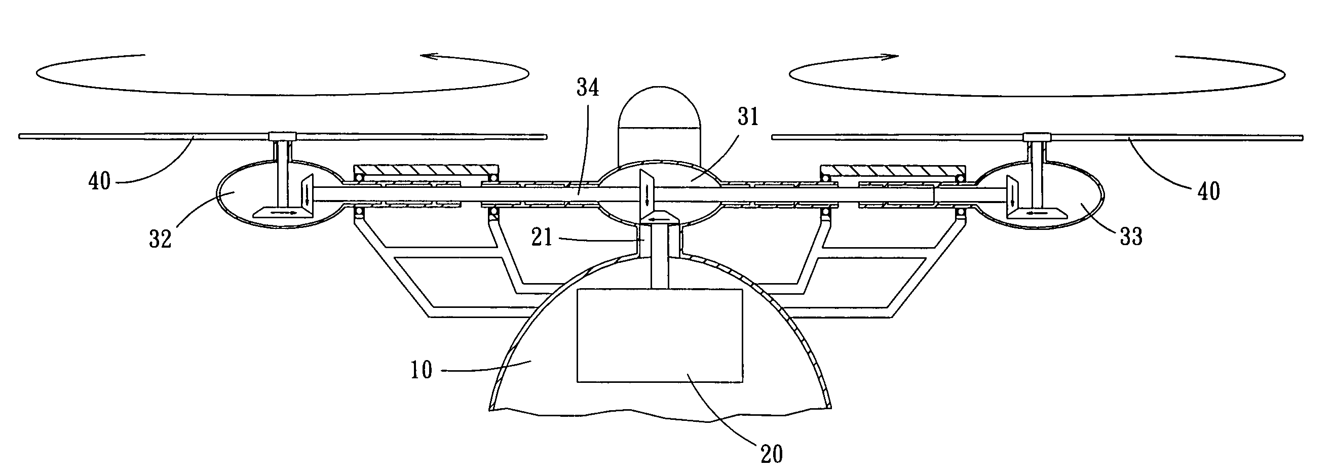
[0013]Another object of the present invention is to provide a dual power helicopter without a tail rotor, wherein a parachute can be loaded, such that when the helicopter is losing power from a mechanical malfunction, it can slowly descend through the parachute, thereby achieving an effect of keeping people and the helicopter safe.
[0014]Accordingly, a dual power helicopter without a tail rotor of the present invention includes a cabin, a power device, a gear box set, a coupling lever set, and two rotors. The power device is located in an interior of the cabin to provide the engine power. The gear box consists of a main gear box and two secondary gear boxes, wherein the main gear box is connected with the power device, the two secondary gear boxes are located at two sides of the main gear box respectively, are coaxial with the main gear box, and are connected with the two rotors, respectively. The two secondary gear boxes are casings which are installed externally and can be freely rotated, in order to control a swinging of the two rotors. On the other hand, the coupling lever set consists of a control lever installed in an interior of the cabin, which is connected to the outer casings of secondary gear boxes through the plurality of coupling levers, such that the pilot in the cabin can manipulate the control lever to drive the two secondary gear boxes through the plurality of coupling levers, thereby controlling the swinging of two rotors.
[0015]However, the two rotors will have different spinning directions through a change of spinning direction resulting from the main gear box and secondary gear boxes, such that the balance of helicopter can be obtained through a left and right spinning of the two rotors, thereby enabling the helicopter to fly more stably. Moreover, through a driving of the coupling lever set, the two secondary gear boxes will have a reverse spinning, to drive the two rotors to be tilted forward and backward, thereby enabling the helicopter to move left or move right through the difference of forward and backward tilting of the two rotors.
[0016]Besides, for the dual power helicopter without a tail rotor of present invention, the engine power created by the power device is completely transmitted to the two rotors through the plurality of gear boxes; therefore, this engine power can be completely provided to the two rotors, thereby largely increasing the power of helicopter.
[0017]Furthermore, for the dual power helicopter without a tail rotor of present invention, a parachute can be further added on a top end of the cabin. The parachute is collected between the two rotors, and it can be ejected outward through air pressure in order to be prevented from being damaged by the two rotors, such that the helicopter can slowly descend through the parachute, thereby achieving an effect of keeping people and the helicopter safe.

Problems solved by technology

However, there is a very serious limitation to the helicopter, resulting from a flight principle of the helicopter.
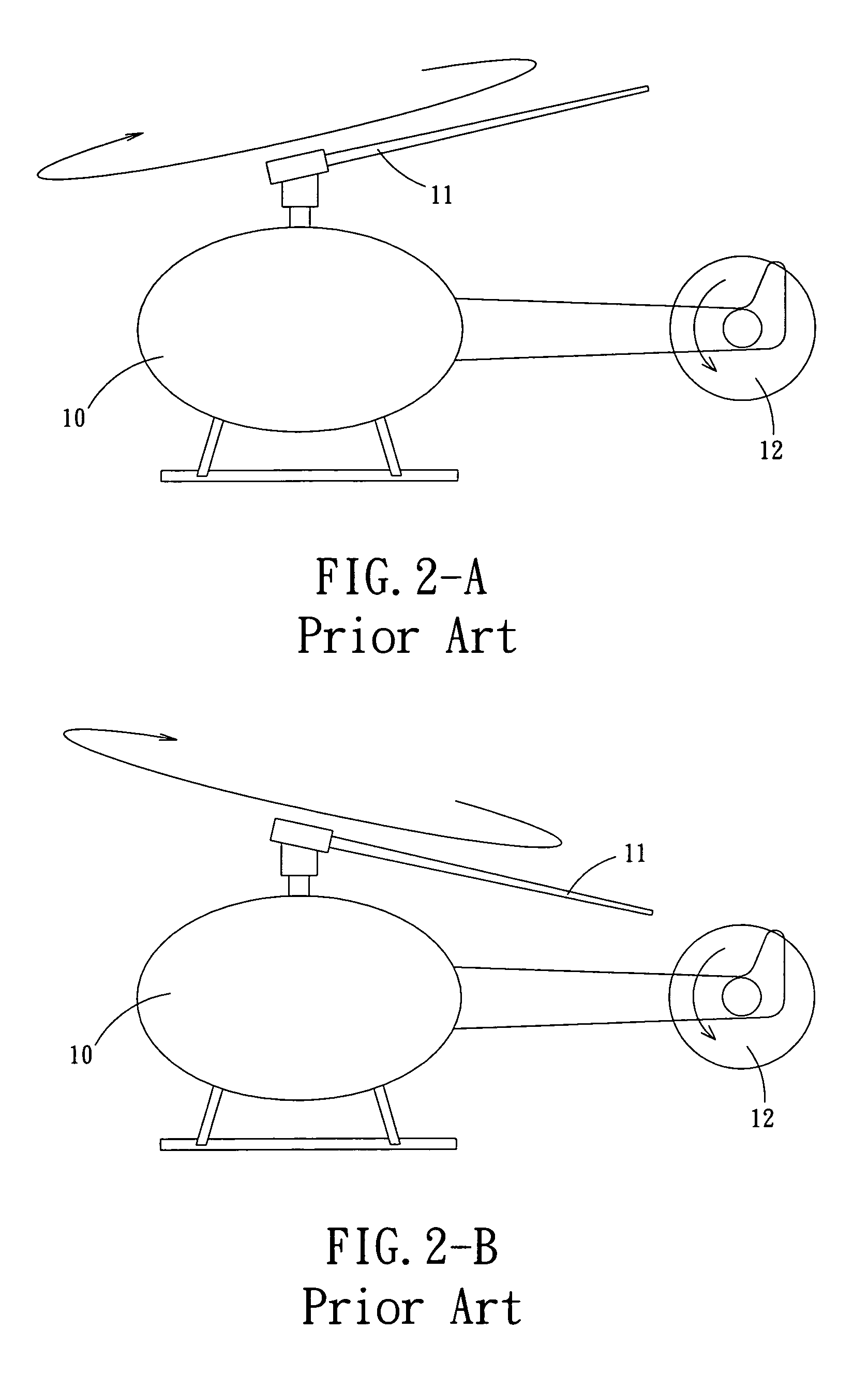
Although the helicopter is a kind of convenient air traffic vehicle, its main rotor 11 is rather complicated, in that in addition to providing the effects of tilting forward and backward, it also needs to provide the effects of tilting leftward and rightward, such that the helicopter can freely fly on a sky.
Moreover, the tail rotor 12 needs to provide the high thrust, and at other times, it needs to provide the low thrust; therefore, the structure of tail rotor 12 is also rather complicated.
Accordingly, due to the complicated structures of main rotor 11 and tail rotor of helicopter, it will be very difficult to drive the helicopter, and is easy to result in an unbalanced flight.
In addition, speed of the helicopter is limited by the main rotor 11.
Moreover, as the conventional helicopter is affected by an installation of the main rotor, it cannot be loaded with an ejection seat or a parachute.
Therefore, when the helicopter is having a mechanical malfunction, it can only be crashed, thereby causing a casualty to the pilot and passengers.

Method used


Image

  • Dual power helicopter without a tail rotor
  • Dual power helicopter without a tail rotor
  • Dual power helicopter without a tail rotor

Examples


Embodiment Construction

[0034]Referring to FIG. 4, a dual power helicopter without a tail rotor comprises a cabin 10, a power device 20 (as shown in FIG. 5), a gear box set 30, two rotors 40, and a coupling lever set 50.

[0035]An interior of the cabin 10 is provided with at least one driving space, and a bottom of the cabin 10 is installed with tires 13.

[0036]Referring to FIG. 5, the power device 20, which is installed in an interior of the cabin 10, primarily provides an engine power, and an upper end of the power device 20 is connected with a clutch 21 which is located at an exterior of top end of the cabin 10.

[0037]Referring to FIG. 5, a main gear box 31 is installed at an upper end of the clutch 21, and two secondary gear boxes, including a left secondary gear box 32 and a right secondary gear box 33, are located at a left and right sides of the main gear box 31, respectively. A same axis 34 is located between the main gear box 31 and the left, right secondary gear boxes 32, 33 to drive the internal gea...


PUM


Abstract

A dual power helicopter without a tail rotor. The dual power helicopter of present invention primarily uses two power devices which can be rotated in opposite directions to control the flight of the helicopter. The two power devices are rotated in the opposite directions by steering gears from a same engine, such that the engine power can be completely transmitted to the two power devices, enabling the engine power to be completely developed, thereby improving performance of the helicopter.

Description

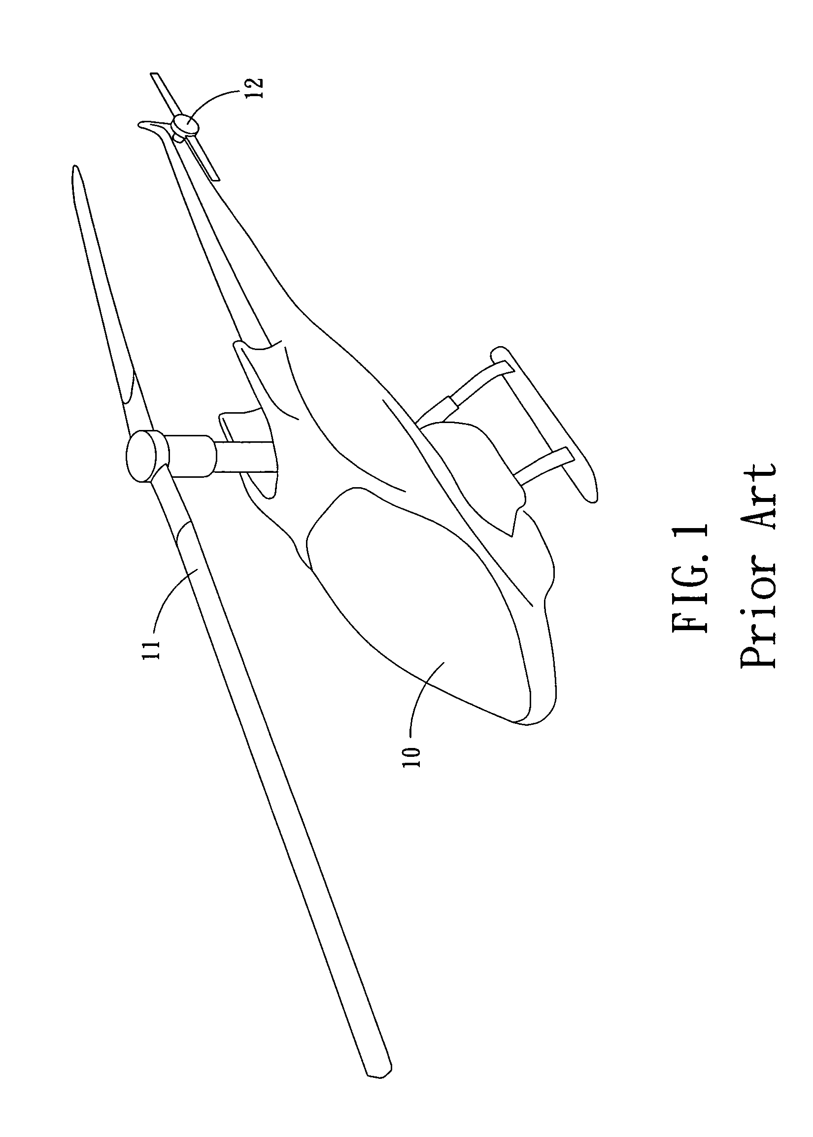
BACKGROUND OF THE INVENTION[0001](a) Field of the Invention[0002]The present invention relates to a dual power helicopter without a tail rotor, and more particularly to a helicopter, an ascending and descending power of which is increased through a dual power, and which is especially provided with high power and safety.[0003](b) Description of the Prior Art[0004]A helicopter has long been a most convenient air traffic vehicle and one of important air forces. The helicopter is widely used in that it can take off and descend vertically without requiring a runway.[0005]However, there is a very serious limitation to the helicopter, resulting from a flight principle of the helicopter.[0006]Referring to FIG. 1, a conventional helicopter includes a cabin 10, an upper end of which is provided with a main rotor 11, and a tail end of which is provided with a tail rotor 12. Axes of the main rotor 11 and the tail rotor 12 are interleaved by 90 degrees, and the two rotors are driven by a same en...

Claims


Application Information

Patent Timeline
Patent Type & Authority Patents(United States)
IPC IPC(8): B64C27/08B64C27/12B64D17/80
CPCB64C27/006B64C27/08B64C27/14
Inventor LI, HONG-FU
Owner LI HONG FU
Why Eureka
Eureka Blog
Learn More