Electrical drive unit

a technology of electric drive and electric motor, which is applied in the direction of electric digital data processing, instruments, and the construction details of electrical apparatus, can solve the problems of reducing the increasing the complexity of the clamping of the transistor, and reducing the problem of the pcb, so as to achieve efficient cooling of the electrical drive unit and efficiently utilize the available area of the pcb

Inactive Publication Date: 2009-06-16
DANAHER MOTION STOCKHOLM AB
View PDF13 Cites 1 Cited by
  • Summary
  • Abstract
  • Description
  • Claims
  • Application Information

AI Technical Summary

Benefits of technology

[0007]An object of the present invention is to provide efficient cooling of an electrical drive unit efficiently utilizing available area of a PCB.
[0009]By providing pressure from one side of the PCB, through a hole in the PCB, to components mounted on the other side of the PCB, efficient cooling of the components is obtained, at the same time achieving efficient utilization of available area on the PCB.

Problems solved by technology

One problem with this method is that you have to place the transistors close to the edge of the PCB even if they electrically would be better placed in other portions of the PCB, such as the centre of the PCB.
Another problem is that the PCB area has to be decreased, for a predetermined assembly size, if the heat sink is situated under the PCB, as one part of the heat sink has to protrude up in order to collect heat from the transistors and transport it down to the heat sink.
Turning the board upside down diminishes this problem, but then the clamping of the transistors gets more complicated instead.
Soldering the transistors in an upright position can also be difficult and requires soldering fixtures.
A problem with this solution is that it takes up a large portion of the PCB area on both sides thereof, since both the transistors and the spring push against the PCB.
A problem with such power modules is that they are expensive and allocate a large PCB area.
A third known way to cool transistors is to use surface mounted power transistors on an additional special PCB built up with a thick aluminum layer at the bottom, which is quite an expensive solution.
The fact that you need two boards with power connections in between them increases production costs and makes the quality more difficult to control.

Method used


Image

  • Electrical drive unit
  • Electrical drive unit
  • Electrical drive unit

Examples


first embodiment

[0020]the present invention will now be described with reference to FIGS. 1-5.

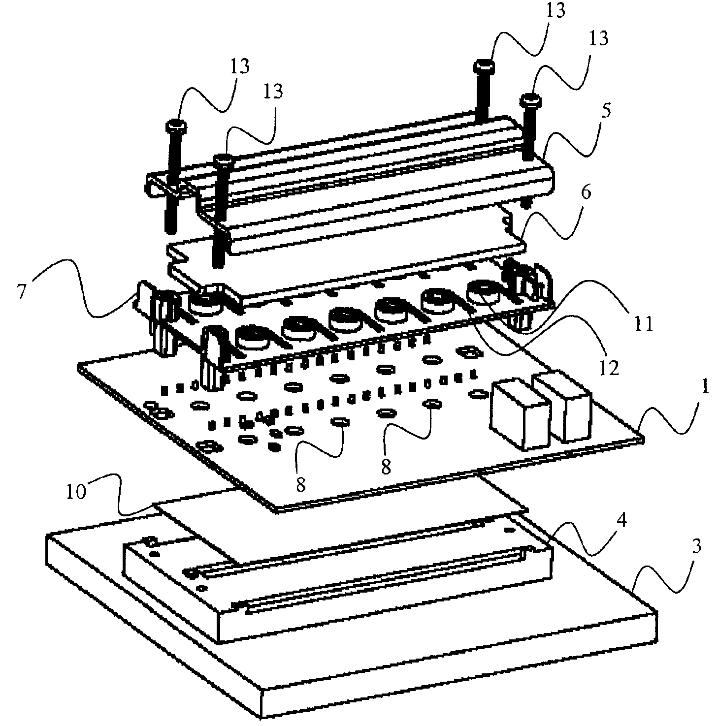
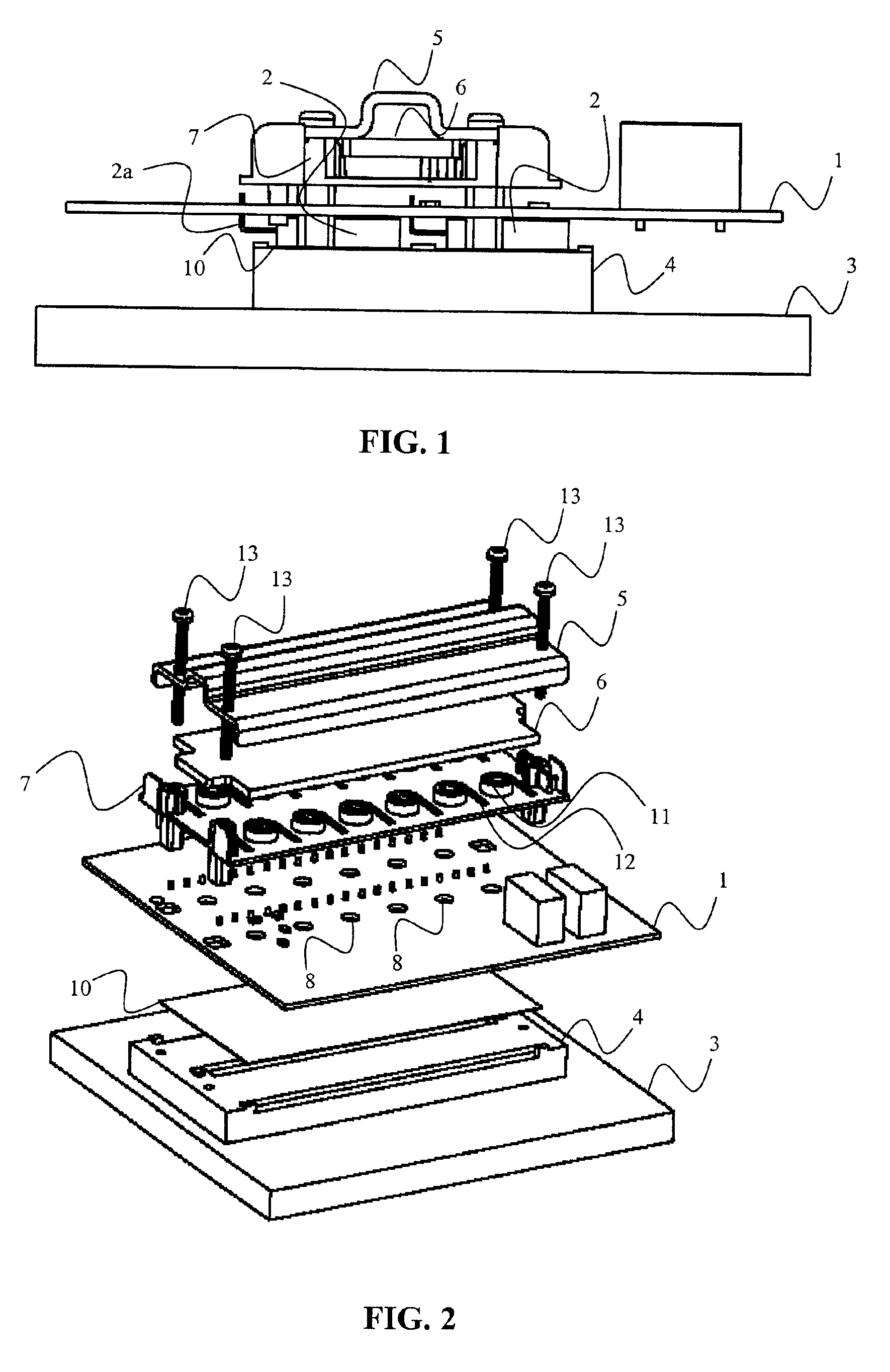
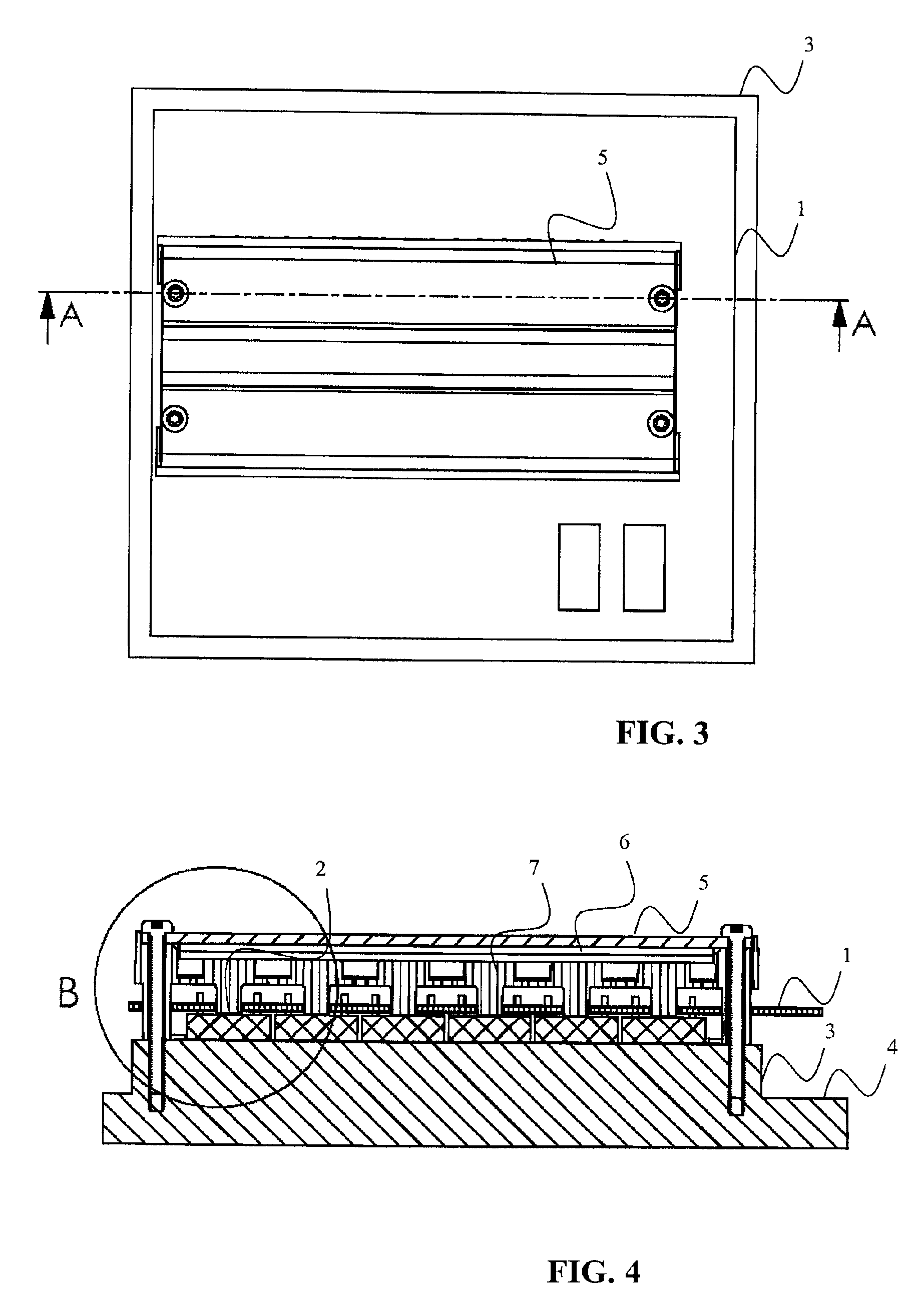
[0021]An electrical drive unit comprises a circuit board (PCB) 1, a plurality of components 2 that need efficient cooling, such as power semiconductors, e.g. power transistors and power diodes, attached to a first side of the PCB 1, and a heat sink 3, 4 arranged on the first side of the PCB 1. The electrical drive unit further comprises a positioning assembly 5, 6, 7 arranged on a second side of the PCB 1, which second side is opposite the first side of the PCB 1. The electrical drive unit preferably also includes a cover (not illustrated) covering the PCB 1 and its plurality of components 2 and the positioning assembly 5, 6, 7 from the surroundings. The positioning assembly 5, 6, 7, the PCB 1 and the heat sink 3, 4 are preferably clamped together, e.g. by screws 13.

[0022]The heat sink 3, 4 is illustrated having a major part 3 and an elevation 4, but the heat sink 3, 4 can have any desired shape, which sha...

second embodiment

[0030]the present invention will now be described with reference to FIG. 6. This second embodiment of the present invention is identical to the first embodiment described above apart from the following.

[0031]The electrical driver unit has half as many components 2 compared to that of the first embodiment described above. The only part of the electrical driver unit that needs to be adapted due to this, with respect to cooling of the components 2, is the second resilient part 6′, which in this case has cut out portions over the unused component positions.


PUM


Abstract

The present invention relates to an electrical drive unit comprising a circuit board, a plurality of components, attached to a first side of the circuit board, a heat sink, arranged on the first side of the circuit board, a positioning assembly, arranged on a second side of the circuit board opposite the first side of the circuit board. The circuit board comprises a plurality of holes between the first and second sides, where through the positioning assembly has a plurality of protrusions arranged against the plurality of components, such that each component of the plurality of components individually is pressed against the heat sink by the positioning assembly.

Description

FIELD OF INVENTION[0001]The present invention relates generally to electrical drive units. Particularly the present invention relates to cooling of a plurality of components in an electrical drive unit.BACKGROUND[0002]An electrical drive unit includes a number of power generating components like transistors. Power transistors generate, apart from power, a lot of heat that needs to be transferred from the components to a heat sink. The best heat-conducting transistors have a metal surface on one side, the inside of which metal surface is connected to the transistor component, and in most cases the transistor component thus has to be electrically isolated from the heat sink. Such isolation is normally achieved by a thin ceramic substrate of aluminum oxide or some heat conductive rubber positioned between the metal surface and the heat sink.[0003]Traditionally these transistors are mounted in an upright position along an edge of a printed circuit board (PCB) and are clamped to a heat s...

Claims


Application Information

Patent Timeline
Patent Type & Authority Patents(United States)
IPC IPC(8): H05K7/20
CPCH05K7/209H05K1/0204H05K7/2029
Inventor NILSON, THORD AGNE GUSTAFKARLSSON, ULF BENGT INGEMAR
Owner DANAHER MOTION STOCKHOLM AB
Why Eureka
Try Eureka