Optical recording medium having a relationship between groove width and track pitch

a technology of optical recording medium and groove width, applied in the field of optical recording and reproducing medium substrate, can solve the problems of inability to directly apply the conventional manufacturing method to the optical disk, the groove width cannot be relatively easily formed, and the production method of ultra-high density optical disk is not only excellent in actual practice, but also satisfactory in yield, so as to achieve satisfactory recording and reproducing characteristics and high accuracy.

Inactive Publication Date: 2009-06-16
SONY CORP
View PDF45 Cites 9 Cited by
  • Summary
  • Abstract
  • Description
  • Claims
  • Application Information

AI Technical Summary

Benefits of technology

[0044]As described above, in the optical recording and reproducing medium substrate according to the present invention, the track pitch of the groove is selected and the ratio between the groove width and the track pitch is optimized, whereby the sufficiently stable push-pull signal amplitude can be obtained in the optical recording and reproducing medium manufactured by using this substrate. Thus, there can be realized the high recording density optical recording and reproducing medium that can hold satisfactory recording and reproducing characteristics.
[0051]Further, according to the present invention, since the groove portion is recorded when the optical recording and reproducing medium manufacturing master is optically recorded and the microminiaturization of the groove width is realized in the succeeding stamper manufacturing process, the optical recording pattern need not be inverted, and accordingly, concavities and convexities of the recording pattern are not inverted unlike the aforementioned cited patent reference 2. Therefore, according to the present invention, it is possible to provide an optical recording and reproducing medium having satisfactory characteristics in which ordinary wobbling grooves in which wobble information are synchronized with each other on the right and left grooves can be formed easily, an optical system for use in reproducing wobble information can be prevented from becoming complex and in which a wobble signal that is satisfactory at a level suitable for actual practice can be reproduced.

Problems solved by technology

However, the high density optical disks of the DVD+RW, DVD-R, DVD-RW and the like have the groove widths smaller than the recording wavelength (413 nm), i.e., the ratios between the groove width and the recording wavelength smaller than 1.0 so that these groove widths cannot be formed relatively easily.
However, there has not yet been proposed an ultra-high density optical disk manufacturing method which is not only excellent in productivity in actual practice but also satisfactory in yield.
Therefore, this conventional manufacturing method cannot be directly applied to an optical disk that intends to increase recording density by reducing the track pitch to less than about 350 nm.
There is then a risk that a leakage of a signal will occur when a wobble signal is reproduced.
Thus, a problem arises, in which it will be difficult to form wobbling grooves at a level suitable for actual practice.

Method used


Image

  • Optical recording medium having a relationship between groove width and track pitch
  • Optical recording medium having a relationship between groove width and track pitch
  • Optical recording medium having a relationship between groove width and track pitch

Examples


##ventive example 1

INVENTIVE EXAMPLE 1

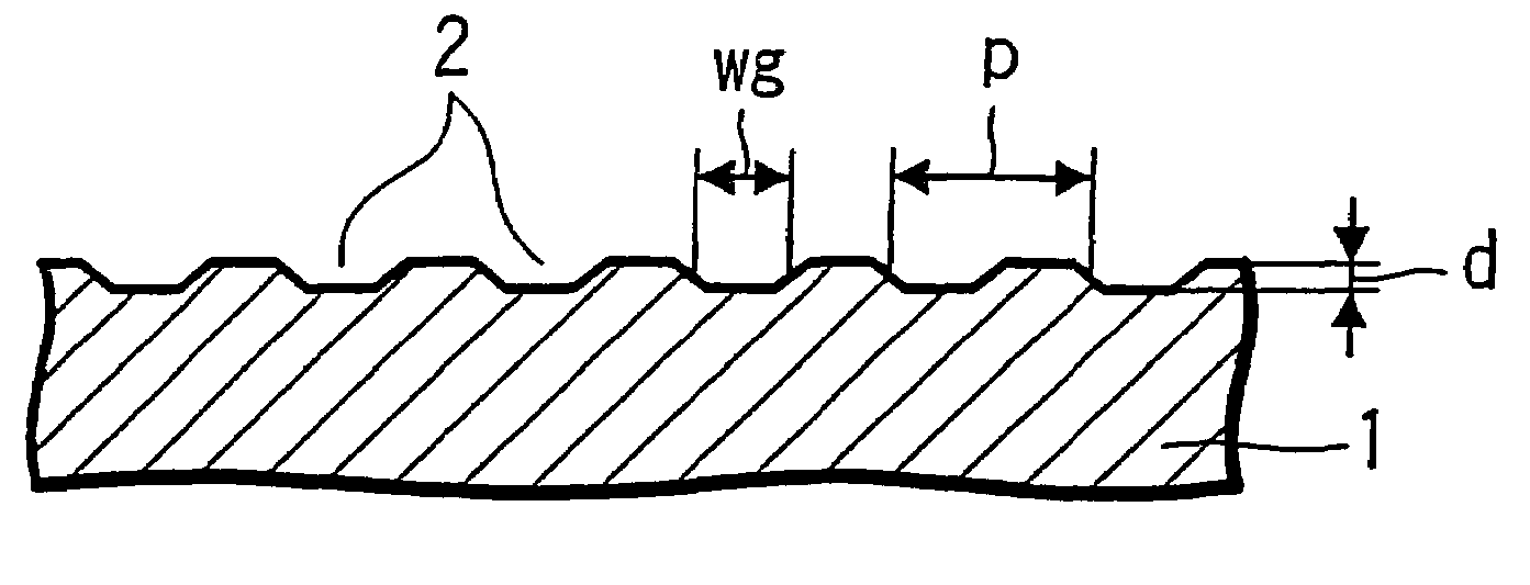
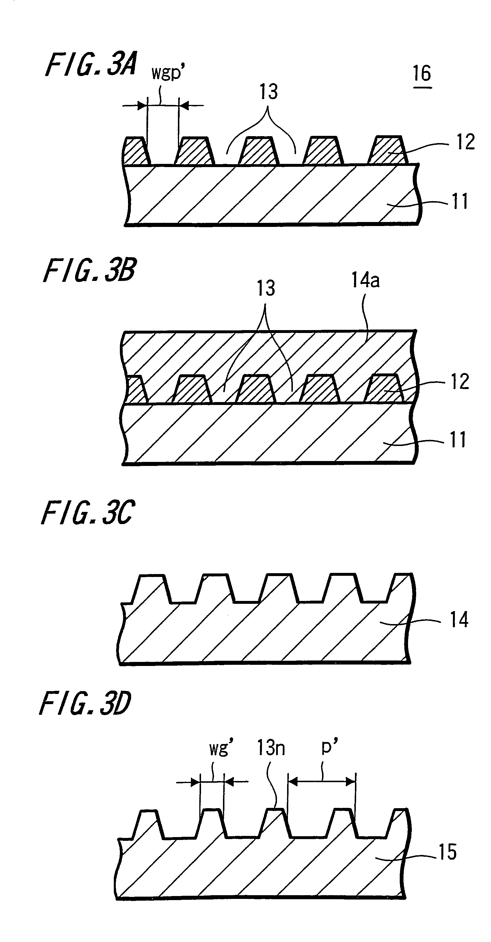
[0118]In the conditions in which a Kr laser (wavelength λ=351 nm) was used as a light source, laser power was controlled so as to fall within a range of from 76% to 100% where 0.6 mJ / m was maximum (100%) and a feed pitch was selected to be 0.350 μm, i.e., a track pitch was selected to be 0.35 μm (350 nm), an optical recording and reproducing medium manufacturing master was manufactured by effecting optical recording on the photoresist. The depth of the groove pattern was set to 15 nm by adjusting the film thickness of the photoresist. A stamper that has been transferred and molded from that master was set to a stamper A. A stamper of which groove width has been microminiaturized by further etching the stamper A under the above-mentioned conditions was set to a stamper AE.

##ventive example 2

INVENTIVE EXAMPLE 2

[0119]In the conditions in which a Kr laser was used as a light source, laser power was controlled so as to fall within a range of from 77% to 100% where 0.25 mJ / m was maximum (100%) and a feed pitch was selected to be 0.300 μm, i.e., a track pitch was selected to be 0.30 μm (300 nm), an optical recording and reproducing medium manufacturing master was manufactured by effecting optical recording on the photoresist. The depth of the groove pattern was set to 20 nm by adjusting the film thickness of the photoresist. A stamper that has been transferred and molded from that master was set to a stamper B. A stamper of which groove width has been microminiaturized by further etching the stamper B under the above-mentioned conditions was set to a stamper BE.

##ventive example 3

INVENTIVE EXAMPLE 3

[0120]In the conditions in which a quartic higher harmonic wave (wavelength λ=266 nm) of a YAG laser was used as a light source, laser power was controlled so as to fall within a range of from 75% to 100% where 0.15 mJ / m was maximum (100%) and a feed pitch was selected to be 0.250 μm, i.e., a track pitch was selected to be 0.25 μm (250 nm), an optical recording and reproducing medium manufacturing master was manufactured by effecting optical recording on the photoresist. The depth of the groove pattern was set to 25 nm by adjusting the film thickness of the photoresist. A stamper that has been transferred and molded from that master was set to a stamper C. A stamper of which groove width has been microminiaturized by further etching the stamper C under the above-mentioned conditions was set to a stamper CE.


PUM

PropertyMeasurementUnit
surface roughnessaaaaaaaaaa
widthaaaaaaaaaa
inclination angleaaaaaaaaaa

Abstract

An optical recording / reproducing medium having grooves formed along recording tracks and used for recording / reproducing when irradiated with light L with a specified wavelength λ, wherein the track pitch p of a groove is at least 200 nm and up to 350 nm, and a ratio wg′ / p between the width wg of a groove and a track pitch p is at least 0.24 and up to 0.67.

Description

TECHNICAL FIELD[0001]The present invention relates to an optical recording and reproducing medium substrate suitable, a manufacturing method of optical recording and reproducing medium manufacturing stamper and an optical recording and reproducing medium manufacturing stamper for use with an optical recording and reproducing medium having grooves formed along recording tracks.BACKGROUND ART[0002]Various kinds of optical disks shaped like discs for optically recording and / or reproducing information are put into practical use as optical recording and reproducing mediums. A read-only optical disk having embossed pits formed on a disk substrate beforehand, a magneto-optical disk for recording data by magneto-optical effect and a phase-change optical disk for recording data by phase-change of a recording film are available as such optical disks.[0003]Of these optical disks, in the optical disk in which data can be written, such as a magneto-optical disk and a phase-change optical disk, i...

Claims


Application Information

Patent Timeline
Patent Type & Authority Patents(United States)
IPC IPC(8): G11B7/24G11B5/00G11B7/00G11B7/007G11B7/2405G11B7/24073G11B7/24076G11B7/24079G11B7/24082G11B7/24085G11B7/26
CPCG11B7/007G11B7/24079G11B7/263G11B7/00G11B7/24082G11B2005/0005G11B7/26
Inventor ENDOH, SOHMEISUZUKI, TADAOSHIMIZU, JUNNAKANO, JUN
Owner SONY CORP
Why Eureka
Try Eureka