Wireless signal distribution system and method

a signal distribution system and wireless technology, applied in the field of wireless communication systems and methods, can solve the problems of reducing operational and maintenance costs, resilience to failure, etc., and achieve the effects of low cost and efficiency, high rf power, and cost-effectiveness

Active Publication Date: 2009-06-16
NEXTG NETWORKS INC
View PDF51 Cites 131 Cited by
  • Summary
  • Abstract
  • Description
  • Claims
  • Application Information

AI Technical Summary

Benefits of technology

[0010]The present invention provides a wireless signal distribution network architecture that provides multiple operators with a low-cost and efficient transport platform for multiple protocols with high RF power at the antennas. This architecture is based on the principle that it must also be cost-effective on initial deployment even though it may only support a single operator at that time. The architecture is therefore expandable and scalable, with each operator or protocol having largely separate equipment that can be retrofitted without service disruption to existing operators or protocols.
[0011]In one embodiment, the present invention comprises a system that uses a single fiber ring to connect one or more BTS hotels with several remote access nodes. Each operator has one or more separate optical wavelengths in either a coarse or a dense wavelength division multiplex (CWDM or DWDM) architecture, which aids system modularity and expandability. Signal flow around the ring can either be uni-directional or bi-directional, the latter providing resilience to a point failure in the ring. Each optical wavelength (or wavelength pair) contains the wireless signal traffic for all remote nodes in the ring for the operator using that particular wavelength in digital form. At each node the incoming signals are electrically demultiplexed and appropriate signals for that node are extracted for conversion to RF. These signals are copied rather than cut so that they are also available at following remote antenna nodes, thereby enabling simulcast operation.

Problems solved by technology

In this architecture, the expensive and complex BTSs are co-located in a benign environment (sometimes known as a BTS hotel), which leads to reduced operational and maintenance costs.
However there are a number of problems with these approaches, in terms of flexibility of service provision and allocation, resilience to failure and transmission efficiency.

Method used


Image

  • Wireless signal distribution system and method
  • Wireless signal distribution system and method
  • Wireless signal distribution system and method

Examples


Embodiment Construction

[0025]In the following description of embodiments, reference is made to accompanying drawings which form a part hereof and in which is shown by way of illustration specific embodiments in which the invention may be practiced. It is to be understood that other embodiments may be utilized and structural changes may be made without departing from the scope of the preferred embodiments of the present invention.

[0026]Each of the embodiments discussed below describes a system with transmit, Tx, (forward link), receive, Rx, (reverse link) and receive diversity, RxD, signals. Other situations may also exist, such as systems with no receive diversity or with the addition of transmit diversity (TxD).

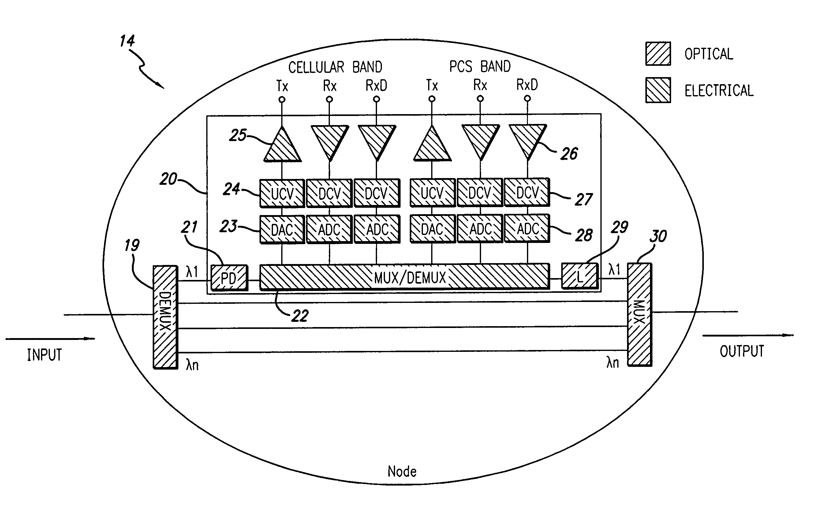
[0027]FIGS. 3 and 4 show one embodiment of the present invention, and the following discussion refers to both FIG. 3 and FIG. 4. FIG. 3 depicts a uni-directional single fiber ring 12 with one BTS hotel 13 and eight remote antenna nodes 14. FIG. 4 illustrates in detail one of the nodes 14. In this ...


PUM


Abstract

A communications system connects one or more BTS hotels with several remote access nodes on a transmission ring. Each operator has one or more separate optical wavelengths. Signal flow around the ring can either be uni-directional or bi-directional. Each optical wavelength (or wavelength pair) contains the wireless signal traffic for all remote nodes in the ring for the operator using that particular wavelength in digital form. At each node, the incoming signals are electrically demultiplexed and appropriate signals for that node are extracted for conversion to RF. These signals are copied rather than cut so that they are also available at following remote antenna nodes, thereby enabling simulcast operation.

Description

BACKGROUND OF THE INVENTION[0001]The present invention relates to wireless communications systems and methods and in particular to a signal distribution network for use in these systems.[0002]The basic structure of a conventional wireless network is depicted in FIG. 1. By way of example, the names' given to the various elements of the network shown in FIG. 1 are taken from the Global System for Mobile communications (GSM) standard, which is the most successful and widespread wireless communications system in the world. It must be noted, however, that similar architectures are used with other wireless protocols.[0003]The core network comprises a number of interconnected mobile switching centers (MSC) 1 which have links to a public switched telephone network (PSTN). Each MSC connects to a number of base station controllers (BSC) 2 and each BSC connects to a number of distributed base transceiver stations (BTS) 3. Each BTS is co-located with an antenna 4 which radiates the wireless sig...

Claims


Application Information

Patent Timeline
Patent Type & Authority Patents(United States)
IPC IPC(8): H04J14/00
CPCH04B10/25754H04B10/25756H04J14/02H04J14/0283
Inventor WAKE, DAVID
Owner NEXTG NETWORKS INC
Why Eureka
Try Eureka