Signal measurement and processing method and apparatus

a signal measurement and processing method technology, applied in the field of measuring and processing electrical parameters, can solve the problems of high noise level, high cost of high precision and stable system, high cost of system production, etc., to avoid erroneous measurements, high noise level, and avoid erroneous measurements

Active Publication Date: 2009-06-16
ULTRA PCS LTD
View PDF57 Cites 5 Cited by
  • Summary
  • Abstract
  • Description
  • Claims
  • Application Information

AI Technical Summary

Benefits of technology

[0017]Thus in accordance with this aspect of the present invention, a measurement and processing method and apparatus is provided in which the need for multiple measurement channels for multiple measured parameters is avoided by the use of a measurement channel which is switched for sequential measurement of the parameters.
[0018]In one embodiment, in order to provide stability and the required level of accuracy in the measurements, a drive signal for generating the measured electrical parameters is known during sequential measurements and the response of the electrical arrangement to the drive signal is relatively stable during the period of the sequential measurements.
[0023]Thus in this embodiment of the present invention, the processing can produce an impedance value or a value representing at least one component of impedance (such as one or a combination of resistance, capacitance and inductance) if required. However, where only an indication of a relative state of impedance or at least one component thereof is required, such as in a proximity sensor, the processing arrangement can more efficiently avoid the determination of an absolute measure of impedance or at least one component thereof and instead merely give an indication of whether a quantity related to the impedance or at least one component thereof is above or below a threshold.
[0025]Thus, this embodiment to the present invention overcomes a limitation of the sequential measurement technique by performing multiple simultaneous measurements of parameters using multiple channels, where each channel is used to obtain measurements of each parameter to provide multiple results which are generated more frequently than for a single measurement channel. This reduces the effect of the delay caused by the sequential measurement technique.
[0033]In one embodiment, the present arrangement is adapted to compare one or more components or derivatives of the third parameter and the fourth parameter to generate the result. For example, a component or derivative of the third parameter can comprise only the real part, only the imaginary part, or a magnitude where the third parameter is complex in these embodiments of the present invention, the multiplication of the first and second parameters by the complex conjugate of the second parameter forms a complex third parameter and a real fourth parameter. This enables the complex third parameter to be compared with the real fourth parameter without the need to take a ratio of the two. However, only the real or imaginary, or magnitude of the complex third parameter need be used in the comparison with the fourth parameter.
[0034]In one embodiment, an estimate of noise in the measurements is determined using averages of the third and fourth parameters over a plurality of measurements. The estimate of noise is used to determine whether to ignore the current comparison of the third and fourth parameters i.e. because of a high noise level. This embodiment to the present invention avoids erroneous measurements due to a high level of noise.

Problems solved by technology

Such a high precision and stable system is expensive to produce because it requires expensive, close-tolerance, and stable components.
In addition, the eddy currents in the target introduce energy loss that appears in the sensor's impedance as an increase in resistance.
Further, the prior art system requires an expensive, close-tolerance, series sense resistor to provide for current sensing.
Such a division is computationally expensive and requires protection from out of range results such as divide by 0.

Method used


Image

  • Signal measurement and processing method and apparatus
  • Signal measurement and processing method and apparatus
  • Signal measurement and processing method and apparatus

Examples


Embodiment Construction

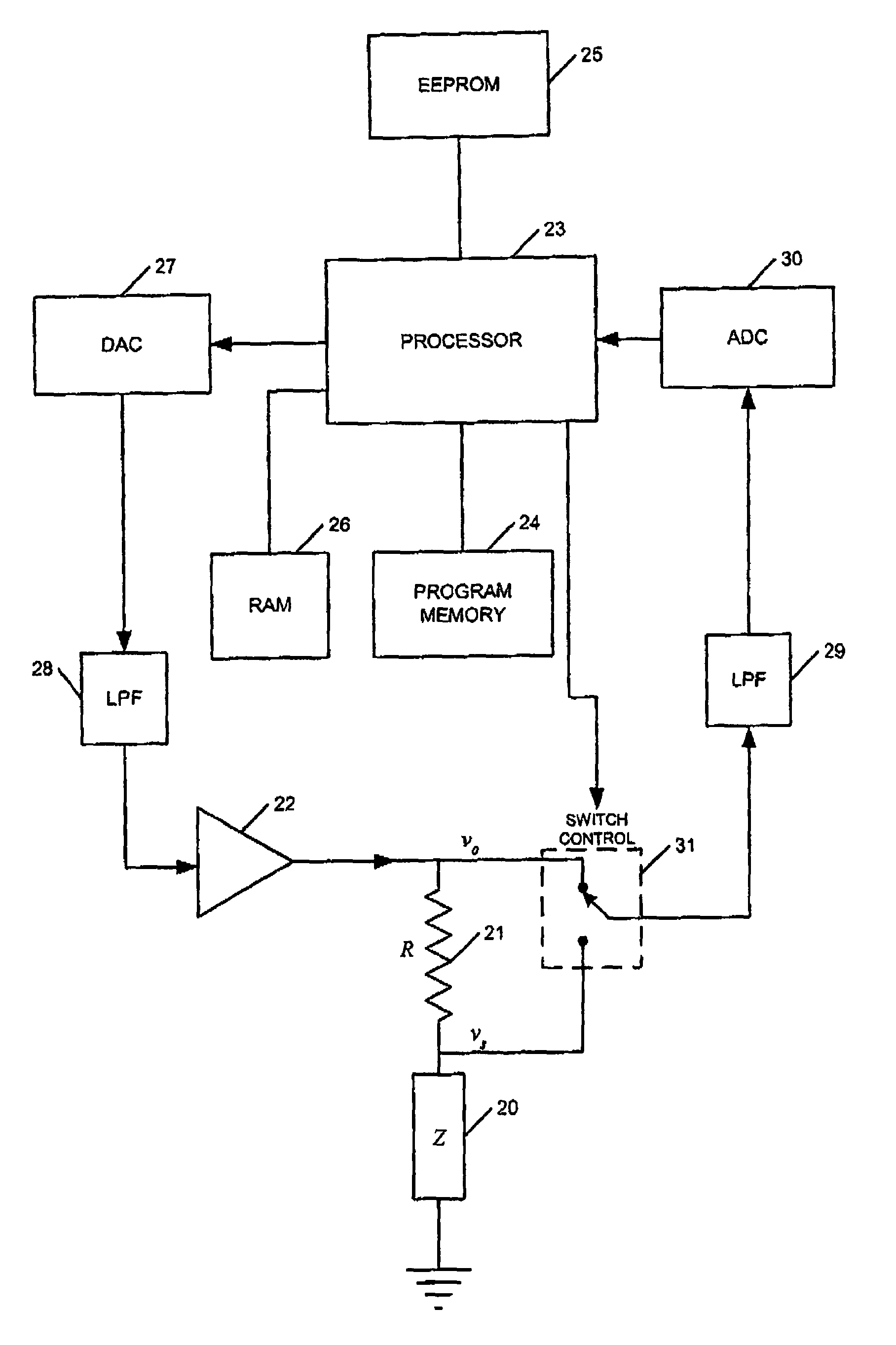
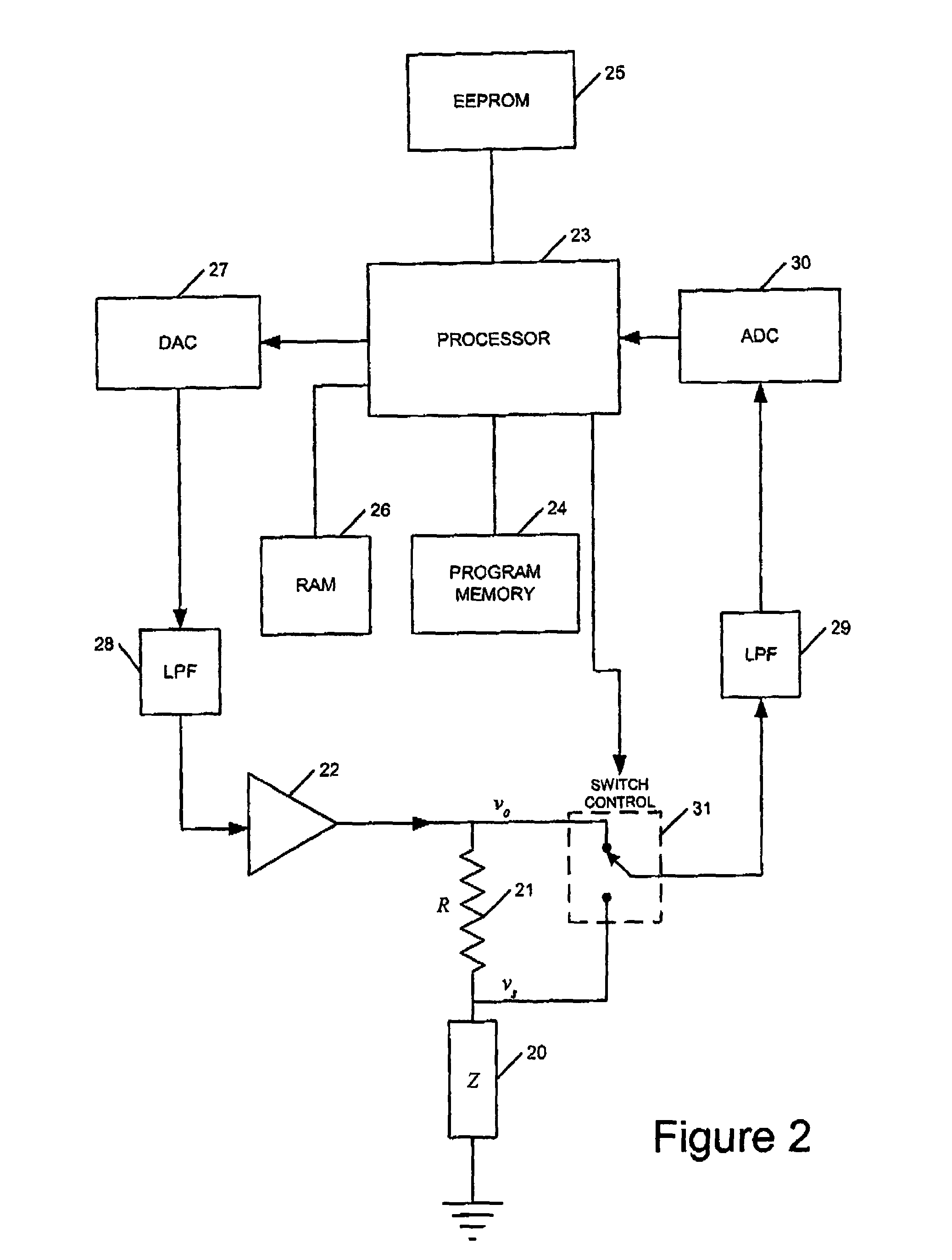
[0047]FIG. 2 illustrates a first embodiment of the present invention for the determination of a change of impedance of a device such as a proximity sensor 20. A load resistance 21 which is temperature and age stable and whose value is known and stored within the processing system is connected in series with the device 20. One end of the load resistance 21 is connected to an amplifier 22, which generates a drive signal comprising at least one sinusoidal signal. The other end of the load resistance 21 is connected to the device 20. A processor 23 is provided with a program memory 24 to control the operation of the processor. An erasable programmable read-only memory (EEPROM) 25 is provided to store data to be used by the processor 23. The data stored in the EEPROM 25 can include waveform generation data comprising a digital representation of at least a part of a waveform, Alternatively this can be stored in the program memory 24 or the random access memory (RAM) 26. The processor 23 i...


PUM


Abstract

Apparatus for generating an output dependent upon the impedance or at least one component of the impedance of a device includes a load component having a known impedance or component thereof for connection in series with the device; a measurement channel for measuring voltages; a switch arrangement connected to the measurement channel for switching the measurement channel to sequentially measure a first voltage on a first side of the load component and a second voltage on a second side of the load component or a voltage difference across the load component; a processing arrangement connected to the measurement channel for processing the sequentially measured voltages to generate an output dependent upon the impedance or at least one component of the impedance of the device; and a signal generating arrangement for generating an electrical signal for application to the series connected load component and device.

Description

FIELD OF THE INVENTION[0001]The present invention generally relates to a method and apparatus for measuring and processing electrical parameters related to an electrical arrangement.BACKGROUND OF THE INVENTION[0002]In some sensing and processing applications more than one quantity has to be measured by an electronic processing system. For some applications the absolute accuracy of the measure of each quantity is less important than the accuracy of one or more quantities relative to one or more other quantities.[0003]For example in a control system where it is necessary to establish whether one quantity is bigger than another with a high degree of precision, so that the correct answer is given even if the larger input is for example only 0.1% bigger than the smaller, it is possible to use a two channel measurement system with absolute accuracy better than 0.05% for each channel in order to achieve the desired result. However, this absolute accuracy must be maintained under variations...

Claims


Application Information

Patent Timeline
Patent Type & Authority Patents(United States)
IPC IPC(8): G01R15/00G01R27/00G01D5/12
CPCG01D5/12
Inventor SLOTHERS, IANLANGLEY, ANDREW
Owner ULTRA PCS LTD
Why Eureka
Try Eureka