NOx augmentation in exhaust gas simulation system

a simulation system and exhaust gas technology, applied in the field of no, can solve the problems of inconvenient use of real engines for long-term testing, high maintenance costs, and inability to conveniently permit the separate evaluation of individual variables of real engines

Active Publication Date: 2009-06-23
SOUTHWEST RES INST
View PDF19 Cites 7 Cited by
  • Summary
  • Abstract
  • Description
  • Claims
  • Application Information

AI Technical Summary

Problems solved by technology

However, the use of a real engine for long term testing can be inconsistent, maintenance intensive, and expensive to operate.
In addition, a real engine does not conveniently permit the separate evaluation of individual variables, such as the effects of various constituents of fuel and oil.

Method used


Image

  • NOx augmentation in exhaust gas simulation system
  • NOx augmentation in exhaust gas simulation system
  • NOx augmentation in exhaust gas simulation system

Examples


second embodiment

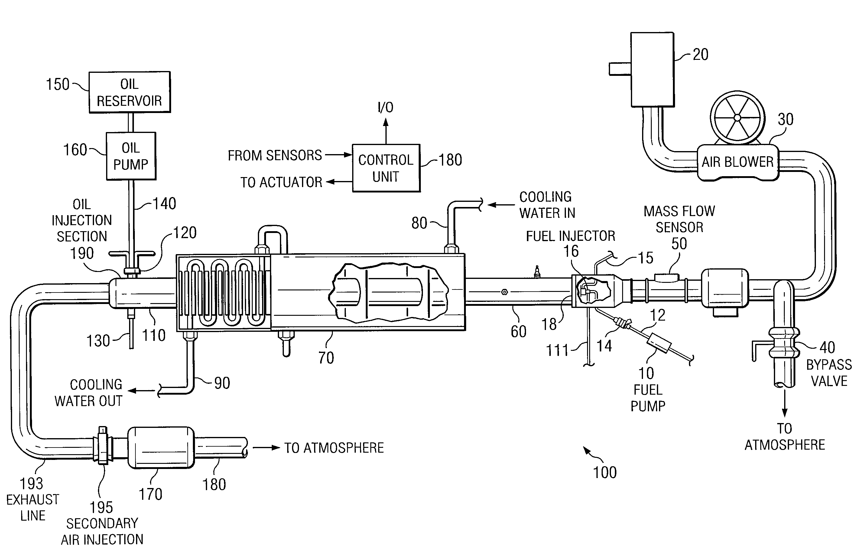
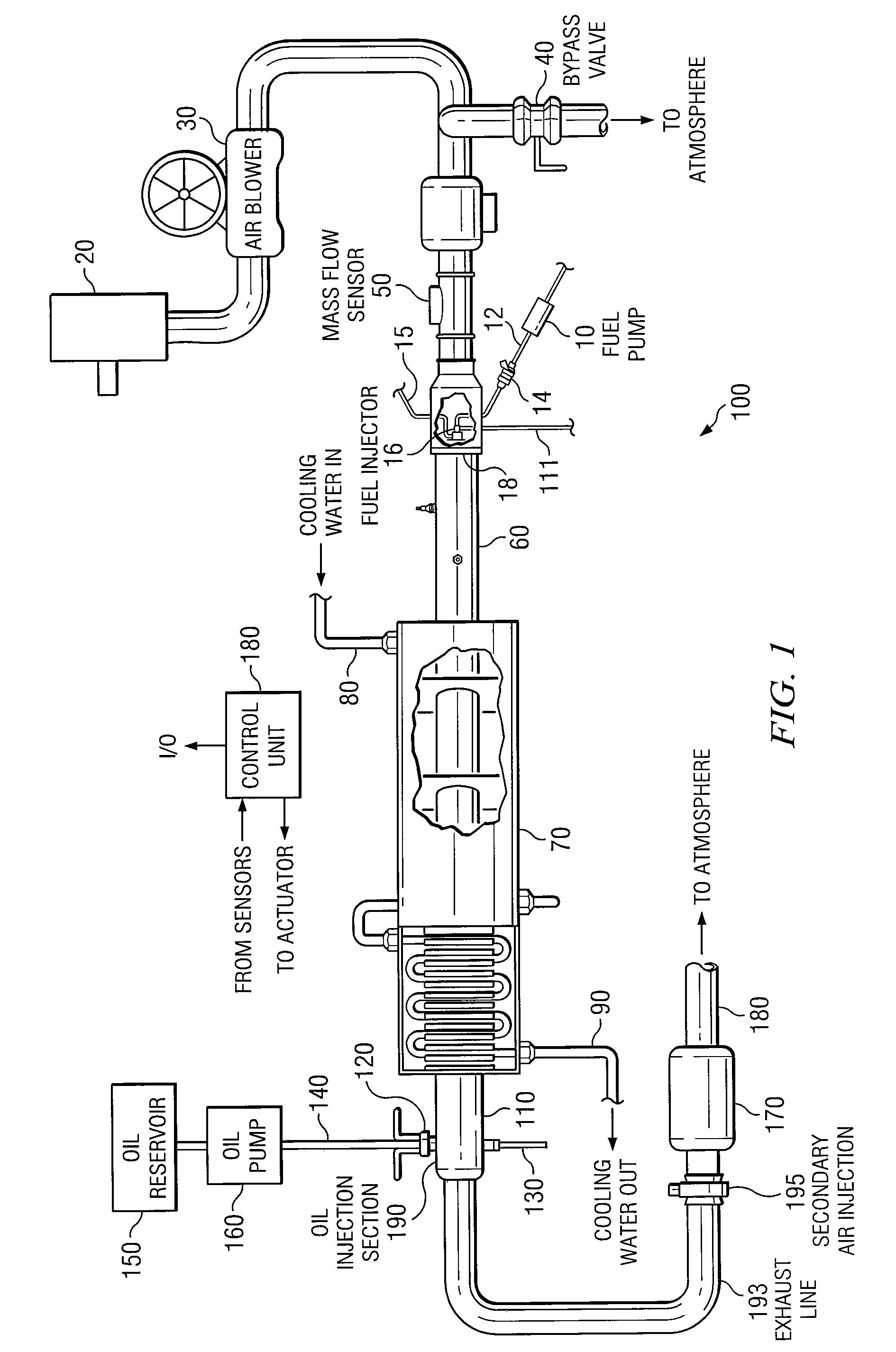
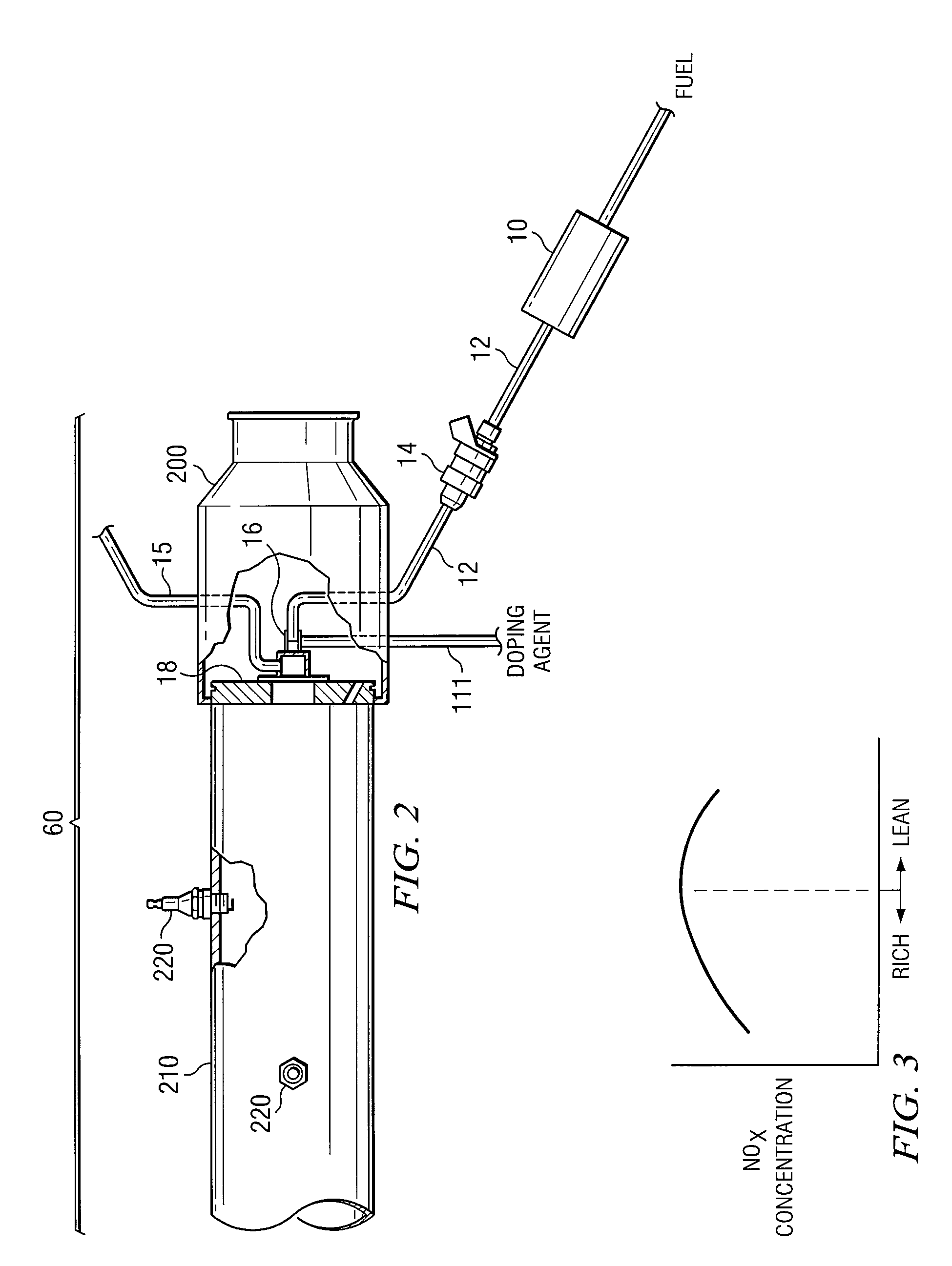
[0064]FIG. 4 illustrates the invention. Like the embodiments of FIGS. 1 and 3A, a nitrogen-containing compound is mixed with fuel prior to reaching the flame of burner 60. However, in the embodiment of FIG. 4, the doping agent is introduced in gaseous form via the air assist line 15. Like the embodiment of FIG. 3A, a valve and a control system may be used to control the amount of doping agent delivered into the air assist line. An example of a suitable doping agent is ammonia gas. In the embodiment of FIG. 4, the doping agent could be nitrogen itself.

third embodiment

[0065]FIG. 5 illustrates the invention. Supplemental NOX is introduced into the exhaust line downstream burner 60. The supplemental NOX is produced by reacting NH3 in an oxidation catalyst 501 at an elevated temperature. A typical temperature at catalyst 501 is 300 degrees Centigrade. For example, a nitrogen-containing compound is delivered to catalyst 501, together with air at a temperature of 300 degrees. The air and NOX out of catalyst 51 is injected directly into the exhaust flow to increase the level of exhaust NOX. The concentration of NOX in the exhaust may be controlled by using a control unit (stand alone or integrated into control system 180) which controls the amount of NOX generated by catalyst 501, such as by varying the air or reactant flow through, or temperature of, catalyst 501. Alternatively, the flow of NOX could be controlled by using a valve 502.

[0066]In sum, any combination of the following methods could be used for augmentation of NOX in the exhaust generated ...


PUM

PropertyMeasurementUnit
diameteraaaaaaaaaa
temperatureaaaaaaaaaa
Durabilityaaaaaaaaaa

Abstract

Various methods and systems for augmenting the amount of NOX in the exhaust of an exhaust flow simulation system. These methods and system can be “combustion” or “post combustion”. A combustion embodiment injects a nitrogen-containing compound (doping agent) into the burner, so that it mixed and combusted with the fuel.

Description

TECHNICAL FIELD OF THE INVENTION[0001]The present application relates in general to systems for simulating the exhaust flow of an engine, for use in testing devices affected by the exhaust.BACKGROUND OF THE INVENTION[0002]As a result of stricter regulations for automotive emissions, it was desired to design a testing apparatus and procedure for testing emissions control devices. Historically, actual internal combustion engines have been used for such evaluations. However, the use of a real engine for long term testing can be inconsistent, maintenance intensive, and expensive to operate. In addition, a real engine does not conveniently permit the separate evaluation of individual variables, such as the effects of various constituents of fuel and oil.[0003]U.S. Patent Pub. No. 2003 / 0079520, entitled “Method and Apparatus for Testing Catalytic Converter Durability” and U.S. Patent Pub. No 2004 / 0007056 A1, entitled Method for Testing Catalytic Converter Durability”, both describe an exh...

Claims


Application Information

Patent Timeline
Patent Type & Authority Patents(United States)
IPC IPC(8): C01B21/20G05D7/00
CPCG01M15/102
Inventor WEBB, CYNTHIA C.SHARP, CHRISTOPHER A.
Owner SOUTHWEST RES INST
Why Eureka
Try Eureka