Piezoelectric electroacoustic transducing device

a transducing device and electroacoustic technology, applied in piezoelectric/electrostrictive transducers, generators/motors, loudspeakers, etc., can solve the problems of further restricting the size of piezoelectric elements, no dimensional space to allow, and the technique cannot be applied to the case, so as to improve the sound quality, the sound pressure level and the sound quality of the piezoelectric electroacoustic transducing device can be improved withou

Inactive Publication Date: 2009-06-23
HOSIDEN CORP
View PDF17 Cites 6 Cited by
  • Summary
  • Abstract
  • Description
  • Claims
  • Application Information

AI Technical Summary

Benefits of technology

[0007]In order to solve the problems, the invention provides a piezoelectric electroacoustic transducing device comprising: a frame; a piezoelectric vibrator in which a piezoelectric element is bonded to a metal plate; and a ring-like support member which supports a peripheral portion of the piezoelectric vibrator on the frame, wherein a concave and convex structure is formed on a surface of the support member. Because of the concave and convex structure of the surface of the support member, while maintaining the external shape of the support member, the support member is provided with a flexibility at which a large displacement of the piezoelectric vibrator is not impeded. When the support member is bonded by using an adhesive agent to the metal plate and the frame of the piezoelectric vibrator, the bonding strength is enhanced, and the molding process can be easily performed without causing the concave and convex structure to be readily collapsed. Therefore, the sound pressure level and the sound quality of the piezoelectric electroacoustic transducing device can be improved without impairing the size, the productivity, the cost, and the like of the device.
[0008]In the invention, preferably, the support member is configured by a resin film in which a mesh-like concave and convex structure is formed on the surface, or an embossed concave and convex structure is formed on the surface. As the molding material of the resin film, for example, a polyethylene terephtalate (PET) resin, a polyethylene naphthalate (PEN) resin, a polyether imide (PEI) resin, a polyimide (PI) resin, a polyamide (PA) resin, or the like is preferable because such a material is excellent in rigidity, easily molded, and low in material cost.

Problems solved by technology

However, this technique cannot be applied to the case where there is no dimensional room space for allowing a large bent portion to be formed between the piezoelectric vibrator and the frame.
Therefore, there is no dimensional room space for allowing a large bent portion to be formed between the piezoelectric vibrator and the frame.
Even when a large bent portion can be formed between the piezoelectric vibrator and the frame, the size increase of the piezoelectric element is further restricted.
Therefore, there arise disadvantages such as that the counter-measure to increase the size of the piezoelectric element to enhance the sound pressure level of the low-frequency range and improve the sound quality cannot be performed, that, in the bent portion, collapse (a dent or the like) easily occurs during an assembling process or vibration, and its function is hardly maintained, and that the molding process is cumbersome and difficult to do, thereby increasing the cost.

Method used


Image

  • Piezoelectric electroacoustic transducing device
  • Piezoelectric electroacoustic transducing device
  • Piezoelectric electroacoustic transducing device

Examples


Embodiment Construction

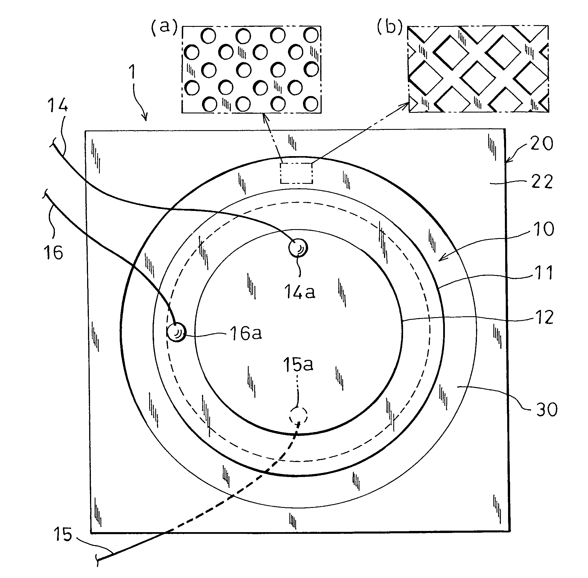
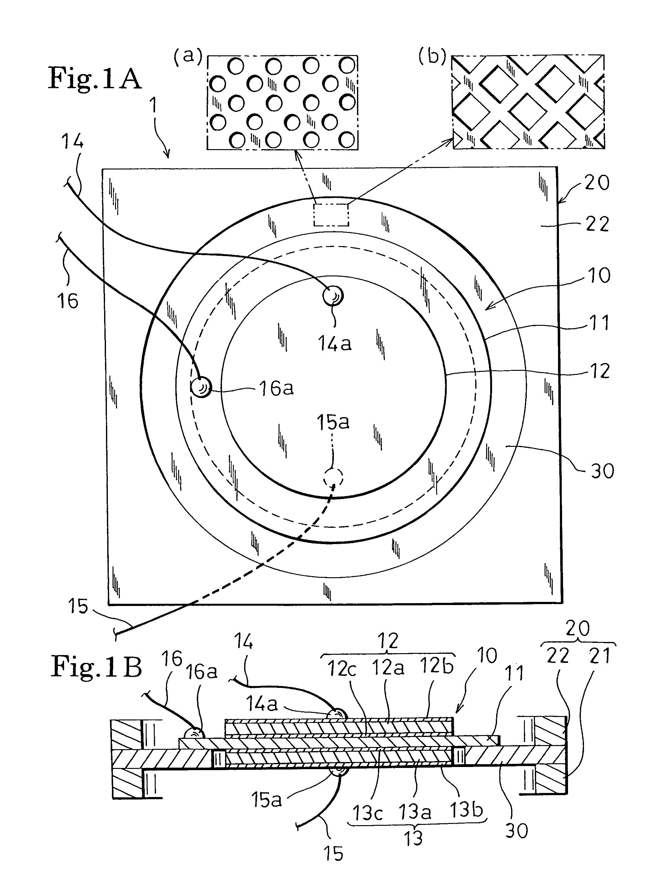
[0014]Hereinafter, a piezoelectric electroacoustic transducing device of an embodiment of the invention will be described with reference to the accompanying drawings. As shown in FIGS. 1A and 1B, the piezoelectric electroacoustic transducing device 1 is configured by: a frame 20; a piezoelectric vibrator 10 in which thin disk-like first and second piezoelectric elements 12, 13 are concentrically bonded to the both faces (front and rear faces) of a thin disk-like metal plate 11, respectively; and a ring-like support member 30 which is disposed between the piezoelectric vibrator 10 and the frame 20, and which supports a peripheral portion of the piezoelectric vibrator 10 on the frame 20.

[0015]The diameter (diameter of the piezoelectric vibrator 10) of the metal plate 11 is larger than the diameters of the first and second piezoelectric elements 12, 13. In FIG. 1, the first and second piezoelectric elements 12, 13 having the same diameter (same surface area) are shown. Alternatively, f...


PUM


Abstract

In order to improve the sound pressure level and the sound quality of a piezoelectric electroacoustic transducing device without impairing the size, the productivity, the cost, and the like of the device, the piezoelectric electroacoustic transducing device 1 has: a frame 20; a piezoelectric vibrator 10 in which piezoelectric elements 12, 13 are bonded to a metal plate 11; and a support member 30 which supports a peripheral portion of the piezoelectric vibrator 10 on the frame 20, and which is made of a resin film such as a ring-like PET resin, and a mesh or embossed concave and convex structure is formed on the surface of the support member 30. While maintaining the external shape of the support member 30, the support member 30 is provided with a flexibility at which a large displacement of the piezoelectric vibrator 10 is not impeded.

Description

BACKGROUND OF THE INVENTION[0001]1. Field of the Invention[0002]The present invention relates to a piezoelectric electroacoustic transducing device which is to be incorporated in an electronic apparatus such as a portable telephone, a PDA, a PC, or a digital camera, and which is used as a sound source.[0003]2. Description of the Prior Art[0004]Patent Reference 1 (Japanese Patent Application Laying Open No. 9-271096) and Patent Reference 2 (Japanese Patent Application Laying Open No. 2001-339793) disclose an invention of a piezoelectric electroacoustic transducing device comprising: a frame; a piezoelectric vibrator in which a piezoelectric element is bonded to a metal plate; and a support member which supports a peripheral portion of the piezoelectric vibrator on the frame. In Patent Reference 1, paragraph [0020] discloses a configuration in which the support member is formed by a thin plate of a resin of, for example, a polyester such as PET or PBT, a polyimide, vinyl chloride, or ...

Claims


Application Information

Patent Timeline
Patent Type & Authority Patents(United States)
IPC IPC(8): H01L41/08
CPCH04R17/00H04R7/20H04R2307/201H04R2307/207H04R2499/11
Inventor FUJIWARA, SATORUNAGATA, YUKA
Owner HOSIDEN CORP
Why Eureka
Try Eureka