Layer-3 network routing with RPR layer-2 visibility

a network routing and visibility technology, applied in the field of communication networks, can solve the problems of internal routing to a given area not knowing the detailed topology, suboptimal performance of the larger network, load imbalance, etc., and achieve the effect of reducing cost factors

Active Publication Date: 2009-06-23
SMART PATH CONNECTIONS LLC
View PDF90 Cites 57 Cited by
  • Summary
  • Abstract
  • Description
  • Claims
  • Application Information

AI Technical Summary

Benefits of technology

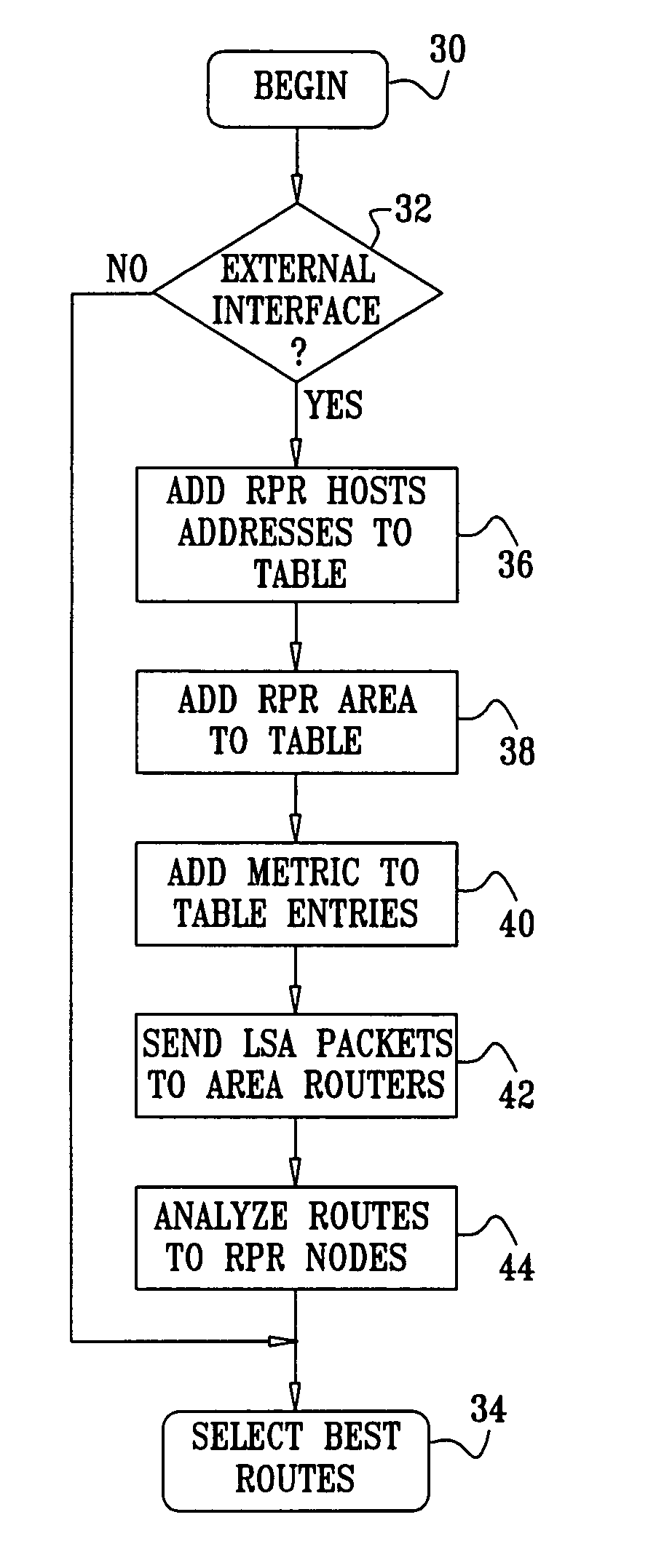
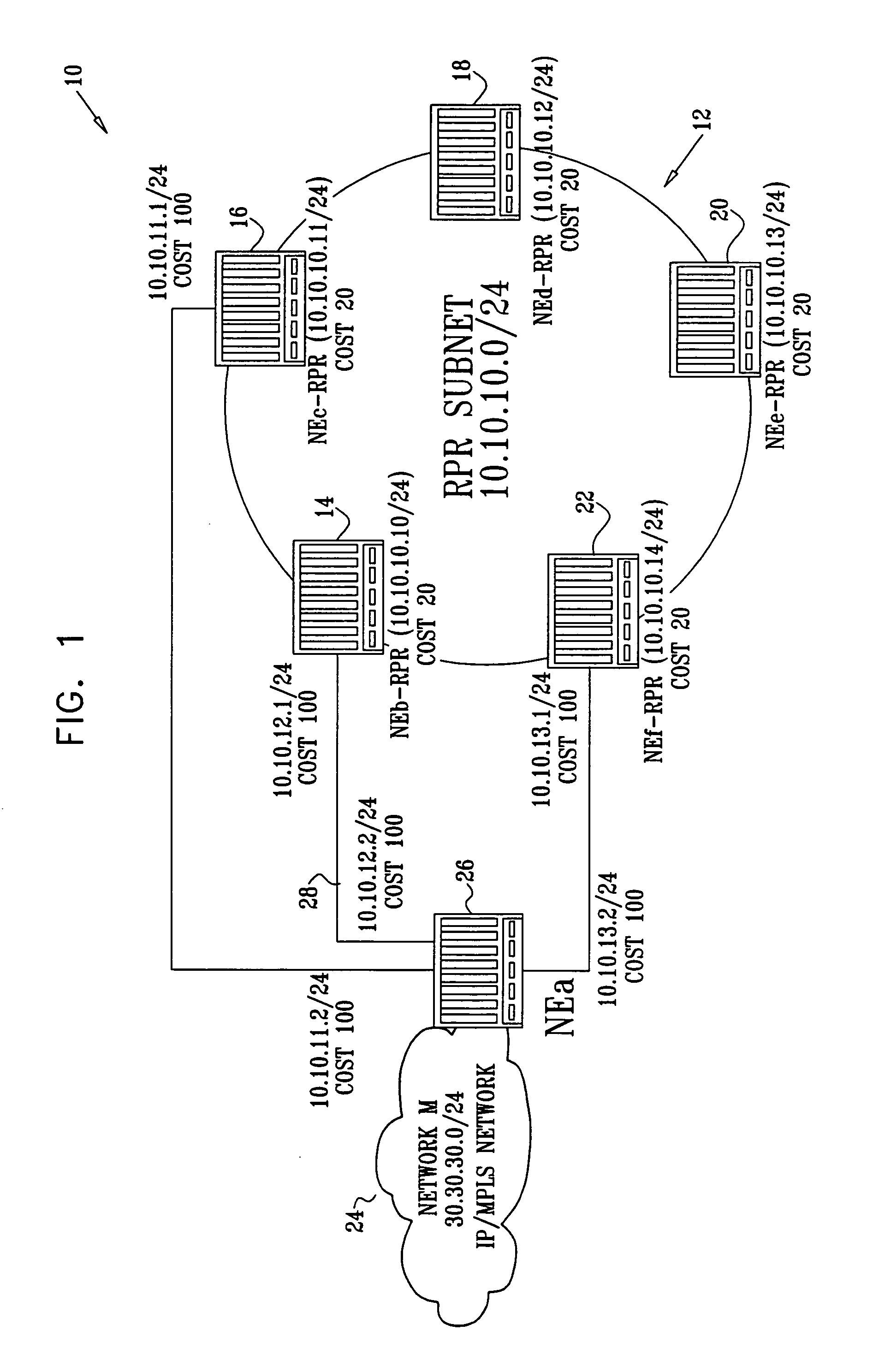
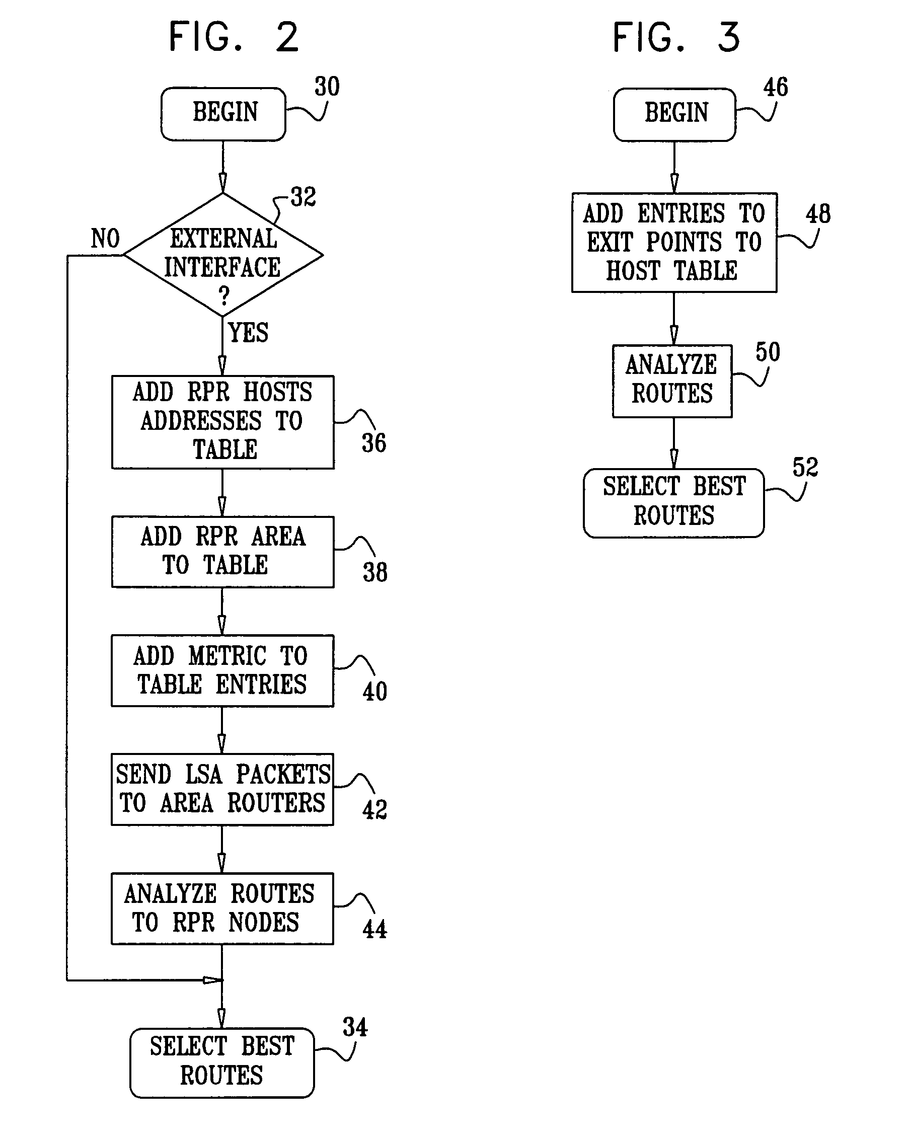
[0019]According to a disclosed embodiment of the invention, methods and systems are provided for the manipulation of layer-3 network nodes, external routers, routing tables and elements of layer-2 ring networks, such as RPR networks, enabling the layer-3 elements to view the topology of a layer-2 ring subnet. This feature permits routers to choose optimal entry points to the layer-2 subnet for different routes that pass into or through the layer-2 subnet. This enables virtual tunnels or routing paths to utilize all existing entry links to the subnet and to minimize cost factors, such as the number of spans required to traverse the subnet from the entry point to a destination node of the subnet.
[0020]In an aspect of the invention, the routing tables of RPR subnet elements are manipulated such that traffic routes originating in or passing through different elements of the RPR subnet and destined for network locations outside the RPR ring have individualized exit nodes. The exit points for the different routes are chosen to minimize cost factors, such as the number of spans required to reach the exit node from each node of the layer-2 subnet.
[0031]In another aspect of the method paths are defined by computing a total cost based on the cost factor and on interface costs that are assigned in the layer-3 network, and selecting the paths so as to minimize the total cost.

Problems solved by technology

Conversely, routers internal to a given area does not know the detailed topology external to the area.
However, the RPR ingress and egress nodes chosen in the operation of automatic routing protocols do not take into account the internal links within the RPR ring, and may therefore cause load imbalances within the RPR subnet, which generally results in suboptimum performance of the larger network.

Method used


Image

  • Layer-3 network routing with RPR layer-2 visibility
  • Layer-3 network routing with RPR layer-2 visibility
  • Layer-3 network routing with RPR layer-2 visibility

Examples


Embodiment Construction

[0045]In the following description, numerous specific details are set forth in order to provide a thorough understanding of the present invention. It will be apparent to one skilled in the art, however, that the present invention may be practiced without these specific details. In other instances well-known circuits, control logic, and the details of computer program instructions for conventional algorithms and processes have not been shown in detail in order not to unnecessarily obscure the present invention.

[0046]Software programming code, which embodies aspects of the present invention, is typically maintained in permanent storage, such as a computer readable medium. In a client-server environment, such software programming code may be stored on a client or a server. The software programming code may be embodied on any of a variety of known media for use with a data processing system. This includes, but is not limited to, magnetic and optical storage devices such as disk drives, ...


PUM


Abstract

Routing tables of OSI layer-3 network elements are modified in order to enable entry to a RPR subnet at different entry points. This enables virtual tunnels or routing paths to utilize all existing entry links to the RPR subnet and to minimize cost factors, such as the number of RPR spans required to traverse the RPR subnet from the entry point to a destination RPR node. The routing tables of RPR subnet elements are modified, such that traffic leaving different elements but destined for the same network location outside the RPR subnet may have individualized RPR exit nodes. The respective RPR exit points for the network elements are chosen to minimize cost factors, such as the number of RPR spans required to reach the exit node from each RPR node.

Description

BACKGROUND OF THE INVENTION[0001]1. Field of the Invention[0002]This invention relates to communications networks. More particularly, this invention relates to methods and systems for improved utilization of communications networks configured as layer-2 ring networks.[0003]2. Description of the Related Art[0004]The meanings of acronyms and certain terminology used herein are given in Table 1.[0005]TABLE 1ASAutonomous SystemATMAsynchronous Transfer Mode. A networktechnology based on transferring data in cellsor packets of a fixed size.FECForwarding equivalence classHDLCHigh-level Data Link ControlIETFInternet engineering task forceIGPInterior Gateway ProtocolIPInternet protocolLANLocal Area NetworkLDPLabel distribution protocolLLCLogical link congtrolLSALink state advertisementLSPLabel-switched pathLSRLabel-switching routerMACMedia access controlMPLSMulti-protocol label switchingMPLS-TEMPLS traffic engineeringOSIOpen System Interconnection. A networkingframework for implementing prot...

Claims


Application Information

Patent Timeline
Patent Type & Authority Patents(United States)
IPC IPC(8): H04L12/28H04L12/42H04L12/46H04L12/56
CPCH04L12/42H04L12/4633H04L45/02H04L45/22H04L45/03
Inventor LEVIT, ALEXAGMON, GIDEONSOLOMON, RONENMENAHEMI, ZVIKA
Owner SMART PATH CONNECTIONS LLC
Why Eureka
Try Eureka