
Magnetic resonance imaging needle antennas

a needle antenna and magnetic resonance technology, applied in the field of radio frequency antennas, can solve the problems of affecting the image quality of neighboring tissue, and the position of the guidewire cannot be very accurately visualized, so as to reduce the risk of chamber or vessel perforation

Inactive Publication Date: 2009-06-23
SURGIVISION
View PDF129 Cites 44 Cited by
  • Summary
  • Abstract
  • Description
  • Claims
  • Application Information

AI Technical Summary

Benefits of technology

[0020]It is further desired by the art to provide an MRI probe that can act as a guidewire to multiple different interventional tools without having to remove the probe from the body to change between tools.
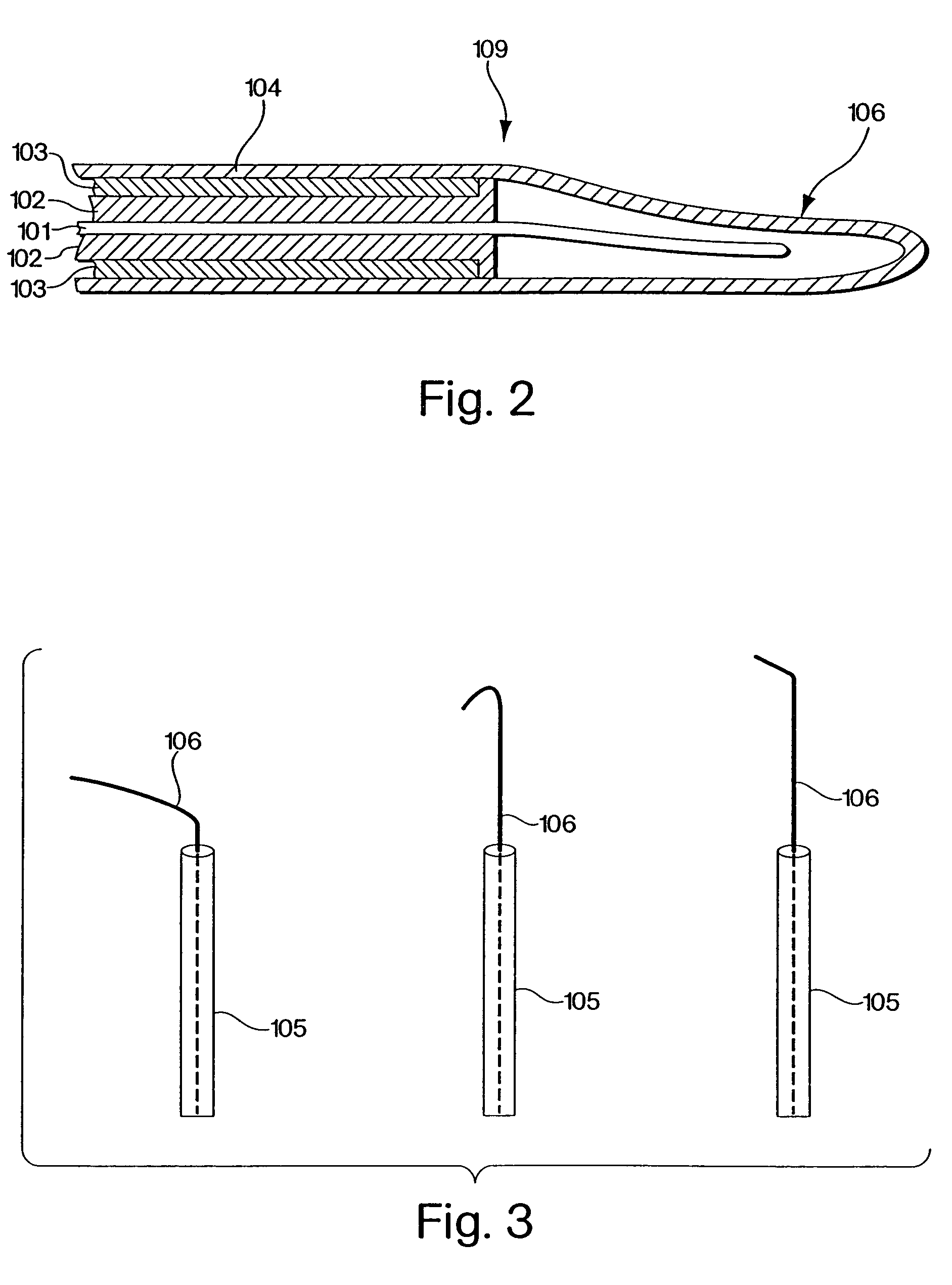
[0023]In a further embodiment of the current invention, the MRI probe's antenna whip is constructed to be flexible and therefore reduce the risk of chamber or vessel perforation.
[0024]In a further embodiment, the invention comprises a system, method, or means, whereby a guidewire probe suitable for use in an MRI machine can have multiple interventional tools switched between and guided by the guidewire probe without having to remove the probe from the subject. This is accomplished in one embodiment of the invention by the design and construction of a probe with a practical connection interface between the probe, the tuning / matching circuitry for tuning the antenna whip, and the MRI machine.

Problems solved by technology

Unfortunately, in these techniques data acquisition speed is often limited and the position of the guidewire cannot be visualized very accurately as it depends on the signal-to-noise ratio (SNR) of a second remote detector coil (antenna) which may be sub-optimal.
In addition, the modification of the material may result in image artifacts distorting the view of neighboring tissue.
These types of probes have also presented problems for clinical applications, since the antennas are often difficult to insert, providing proper shielding from body fluids and tissues has been difficult, and avoiding injury to patients has at times required suboptimally sized probes to be used.

Method used


Image

  • Magnetic resonance imaging needle antennas
  • Magnetic resonance imaging needle antennas
  • Magnetic resonance imaging needle antennas

Examples


Embodiment Construction

[0054]This disclosure will discuss the invention primarily in terms of a loopless whip antenna for use with a guidewire probe that is suitable for vascular procedures on human subjects in a conventional MRI machine designed for medical use. This description does not, however, limit the scope of this invention. In particular, the invention can comprise any type of probe with any type of MRI antenna whether a whip antenna or not and whether of looped, loopless or of other design which is suitable for use as a guidewire as is understood in the art. The invention can also comprise any type of probe or other device for insertion into a subject, whether or not for use as a guidewire, that comprises a helical coil being used as an antenna. This includes, but is not limited to; any type of biopsy device; any type of interventional tool; any type of probe or device which could be used simultaneously to an interventional tool; any type of catheter, known now or later discovered, including, bu...


PUM


Abstract

The invention describes a system, method, and means for an MRI transseptal needle that can be visible on an MRI, can act as an antenna and receive MRI signals from surrounding subject matter to generate high-resolution images and can enable real-time active needle tracking during MRI guided transseptal puncture procedures.

Description

REFERENCE TO PRIOR APPLICATIONS[0001]This application is a continuation of U.S. patent application Ser. No. 09 / 775,338, filed Feb. 1, 2001, now U.S. Pat. No. 6,606,513, which claims the benefit of U.S. Provisional Application Ser. No. 60,178,933, filed Feb. 1, 2000, and which is a continuation-in-part of U.S. patent application Ser. No. 09 / 536,090, filed Mar. 24, 2000, now U.S. Pat. No. 6,675,033, which claims priority to U.S. Provisional Application Ser. No. 60 / 129,364, filed Apr. 15, 1999. The entire disclosure of each application is hereby incorporated by reference.BACKGROUND OF THE INVENTION[0002]1. Field of the Invention[0003]This invention relates to the field of radio frequency antennas. More particularly to the use of a radio frequency antenna as a transseptal needle for use in vivo in conjunction with magnetic resonance imaging techniques.[0004]2. Description of Related Art[0005]Magnetic resonance imaging (MRI) is a well known, highly useful technique for imaging matter. It...

Claims


Application Information

Patent Timeline
Patent Type & Authority Patents(United States)
IPC IPC(8): A61B5/055G01R33/28G01R33/34H01Q1/36H01Q1/40H01Q1/44H01Q11/08
CPCG01R33/285G01R33/287G01R33/34053G01R33/34084H01Q1/36H01Q1/362H01Q1/40H01Q1/44H01Q11/08
Inventor LARDO, ALBERT C.MCVEIGH, ELLIOTT R.HALPERIN, HENRY R.
Owner SURGIVISION
Learn More