Zoom lens system and image-pickup apparatus

a zoom lens and image-picking technology, which is applied in the field of zoom lens system and image-picking apparatus, can solve the problems of increased lens diameter, insufficient reduction of lens diameter, and difficulty in reducing lens diameter, so as to achieve high magnification and reduce lens diameter

Inactive Publication Date: 2009-06-30
SONY CORP
View PDF9 Cites 0 Cited by
  • Summary
  • Abstract
  • Description
  • Claims
  • Application Information

AI Technical Summary

Benefits of technology

[0020]By taking into consideration the above-described problems, a zoom lens according to an embodiment of the present invention has a high magnification, is suitable for decreasing the lens diameter, and is capable of shifting an image.
[0023]The zooms lens system according to an embodiment of the present invention has high magnification, is suitable for reducing the diameter of lenses, and is capable of shifting an image.

Problems solved by technology

For such a known zoom lens system capable of shifting an image, there is a problem in that it is difficult to reduce the diameter of the lenses.
However, since functions required for aberration correction are concentrated in the third lens unit, the diameter of the lenses cannot be sufficiently reduced.
As a result, the diffusion effect of the second lens unit must be weakened, causing an increase in the lens diameter.
However, the number of driving mechanisms must be increased, causing the structure of the barrel to be complex and increasing the barrel diameter.
Therefore, the size of the zoom lens system cannot be sufficiently reduced.

Method used


Image

  • Zoom lens system and image-pickup apparatus
  • Zoom lens system and image-pickup apparatus
  • Zoom lens system and image-pickup apparatus

Examples


first embodiment

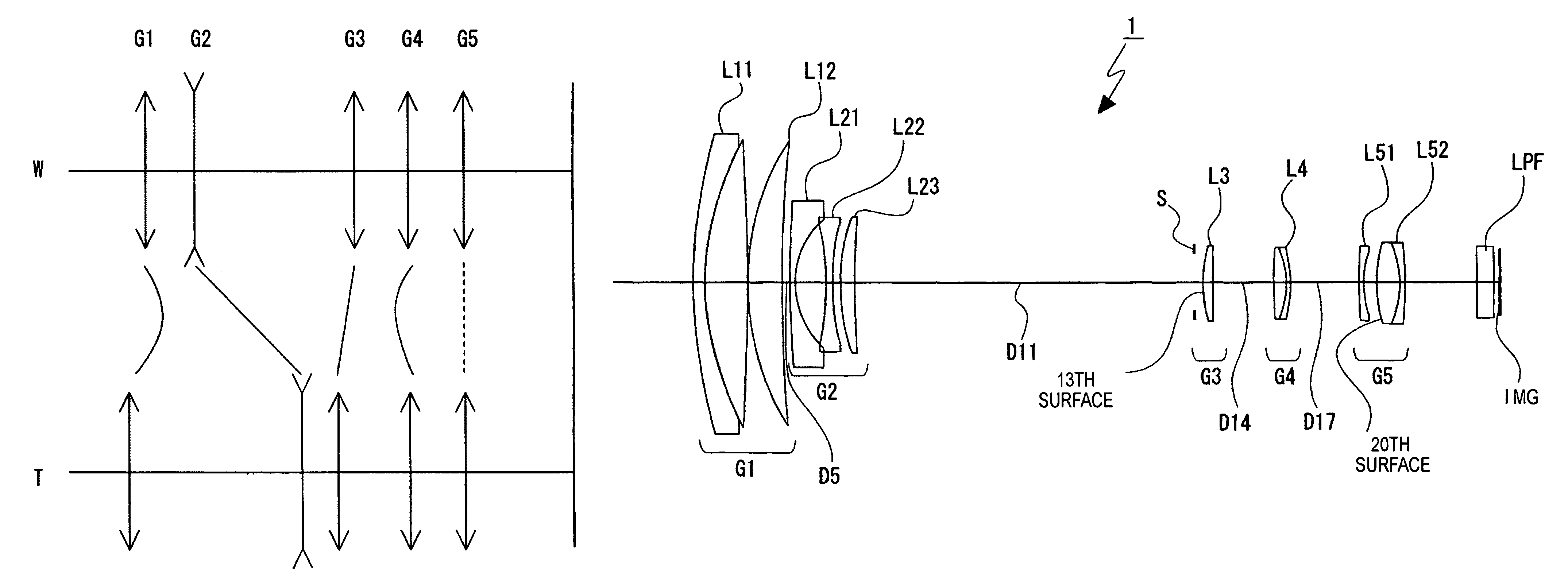
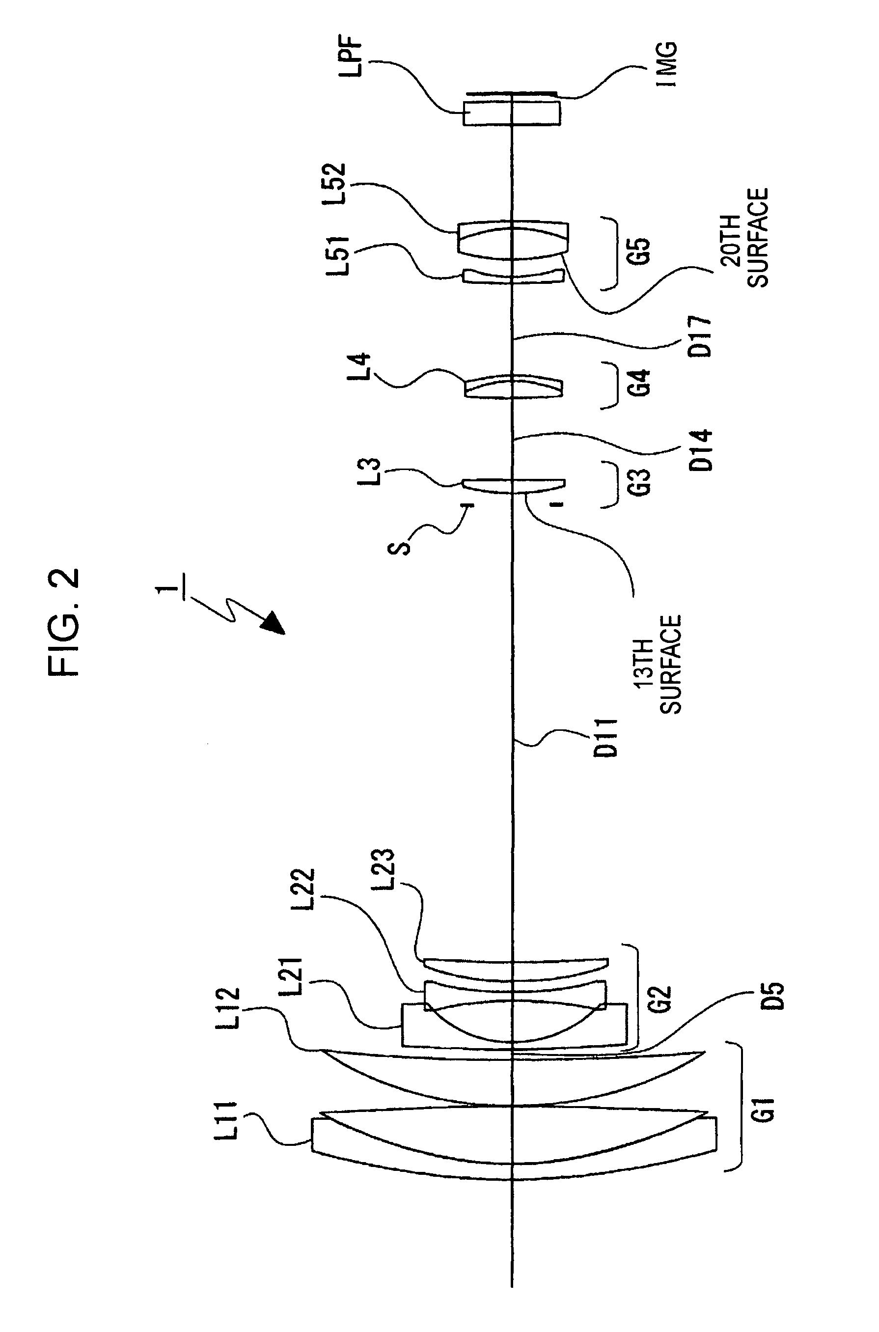
[0125]FIG. 2 illustrates the lens configuration of a zoom lens system according to the present invention. A first lens unit G1 is configured of a cemented lens L11 of a negative meniscus lens having a convex surface facing the object and a positive lens having convex surface facing the object; a second lens unit G2 is configured of a negative meniscus lens L21 having a concave surface facing the image, a negative lens L22 whose surfaces are both concave, and a positive meniscus lens having a convex surface having a convex surface facing the object; a third lens unit G3 is configured of a positive meniscus lens L3 having an aspherical convex surface facing the object; a fourth lens unit G4 is configured of a cemented lens L4 of a positive lens whose surfaces are both convex and a negative meniscus lens having a concave surface facing the object; and a fifth lens unit is configured of a negative meniscus lens 51 having a concave surface facing the image and a cemented lens L52 of a po...

second embodiment

[0139]FIG. 9 illustrates the lens configuration of a zoom lens system according to the present invention. A first lens unit G1 is configured of a cemented lens L11 of a negative meniscus lens having a convex surface facing the object and a positive lens having convex surface facing the object, and a positive lens L12 having a convex lens facing the object; a second lens unit G2 is configured of a negative meniscus lens L21 having a concave surface facing the image, a negative lens L22 whose surfaces are both concave, and a positive meniscus lens L23 having a convex surface facing the object; a third lens unit G3 is configured of a positive meniscus lens having an aspherical convex surface facing the object; a fourth lens unit G4 configured of a cemented lens L4 of a positive lens having an aspherical surface facing the object and whose surfaces are both convex and a negative meniscus lens having a concave surface facing the object; and a fifth lens unit G5 is configured of a negativ...

third embodiment

[0153]FIG. 16 illustrates the lens configuration of a zoom lens system according to the present invention. A first lens unit G1 is configured of a cemented lens L11 of a negative meniscus lens having a convex surface facing the object and a positive lens having convex surface facing the object, and a positive lens L12 having a convex lens facing the object; a second lens unit G2 is configured of a negative meniscus lens L21 having a concave surface facing the image, a negative lens L22 whose surfaces are both concave, and a lens L23 whose surfaces are both convex; a third lens unit G3 is configured of a positive lens having an aspherical surface facing the object and shoes surfaces are both convex; a fourth lens unit G4 configured of a cemented lens L4 of a positive meniscus lens having an aspherical surface facing the object and a convex surface having the image and a negative meniscus lens having a concave surface facing the object; and a fifth lens unit G5 is configured of a nega...


PUM


Abstract

A zoom lens system includes, in order from the object side, a first lens unit having positive refractive power, a second lens unit having negative refractive power, a third lens unit having positive refractive power, a fourth lens unit having positive refractive power, and a fifth lens unit. When the lens positions change from the wide-angle end to the telephoto end, at least the first to fourth lens units are movable in an optical axis direction. The fifth lens unit includes a negative subunit having negative refractive power and a positive subunit having positive refractive power and being disposed on the image side of the negative subunit with a predetermined air gap the negative subunit and the positive subunit, and is capable of shifting the image by shifting the positive subunit in a direction substantially orthogonal to the optical axis.

Description

CROSS REFERENCES TO RELATED APPLICATIONS[0001]The present invention contains subject matter related to Japanese Patent Application JP 2006-033767 filed in the Japanese Patent Office on Feb. 10, 2006, the entire contents of which are incorporated herein by reference.BACKGROUND OF THE INVENTION[0002]1. Field of the Invention[0003]The present invention relates to a non-obvious zoom lens system and an image-pickup apparatus. More specifically, it relates to a zoom lens system capable of shifting an image by shifting part of a lens in a direction substantially orthogonal to the optical axis and relates to an image-pickup apparatus including the zoom lens system.[0004]2. Description of the Related Art[0005]There is a known recording method for a camera in which the light intensity of an image of an object that is formed on an image-pickup element surface by an image-pickup element using a photoelectric conversion element, such as a charge coupled device (CCD) or a complementary method-oxi...

Claims


Application Information

Patent Timeline
Patent Type & Authority Patents(United States)
IPC IPC(8): G02B15/14G02B27/64
CPCG02B15/173G02B27/646G02B15/145129G02B13/009G02B3/0087G03B17/12H04N23/55
Inventor OHTAKE, MOTOYUKI
Owner SONY CORP
Why Eureka
Try Eureka