Recording disk drive having shroud

a technology of recording disk and shroud, which is applied in the direction of recording information storage, electrical apparatus construction details, instruments, etc., can solve the problems of insufficient airflow, inability of filters inability to sufficiently catch dust in airflow, so as to suppress airflow turbulence, effectively catch dust, and suppress the effect of vibration of recording disk

Inactive Publication Date: 2009-06-30
TOSHIBA STORAGE DEVICE CORP
View PDF16 Cites 11 Cited by
  • Summary
  • Abstract
  • Description
  • Claims
  • Application Information

AI Technical Summary

Benefits of technology

[0007]It is accordingly an object of the present invention to provide a recording disk drive capable of improving the efficiency in catching dust in airflow and of suppressing vibration of a recording disk.
[0009]The recording disk drive of the type allows generation of airflow along the front and back surfaces of the recording disk during the rotation of the recording disk. The airflow flows outward toward the outer periphery of the recording disk based on the centrifugal force of the rotating recording disk. The first and second shroud surfaces and the shroud plate are opposed to the outward peripheral surface of the recording disk. The shroud plate serves to establish the continuity of the first and second shroud surfaces. The first and second shroud surfaces and the shroud plate serve to reliably suppress turbulence of the airflow. Vibration of the recording disk is suppressed than ever.
[0010]Moreover, the inflow opening is located in a space between the first and second shroud surfaces. The rectifier plate is located downstream of the inflow opening. The upstream end of the rectifier plate extends in the radial direction over the surface of the recording disk. The rectifier plate serves to direct the airflow flowing along the first shroud surface to the inflow opening. A larger amount of airflow can be introduced into the inflow opening. Furthermore, the shroud plate is located inside the inflow opening. The shroud plate extends along an imaginary plane perpendicular to the rotation axis of the recording disk. The airflow is allowed to efficiently flow into the airflow passage through the inflow opening. The airflow is prevented from staying at the inflow opening. The dust catcher can in this manner be exposed to a smooth airflow. The dust catcher is allowed to enjoy an efficient catch of dust out of the airflow.
[0012]The shroud surface serves to suppress turbulence of airflow in the recording disk drive of the type. Vibration of the recording disk is thus suppressed. Moreover, the airflow flows along the airflow guide surface. An airflow passage is in this manner established along the airflow guide surface. Moreover, since the protrusions enable enlargement of area in the dust catcher without increasing the occupied space. The dust catcher is thus allowed to achieve an efficient catch of dust.
[0013]In this case, the protrusions of the dust catcher may be terminated within the airflow passage. The airflow is thus allowed to suppress stay of airflow as much as possible inside the airflow passage. The dust catcher is allowed to reliably receive airflow of a sufficient current velocity. The dust catcher catches dust in an improved manner.
[0015]The shroud surface serves to suppress turbulence of airflow in the recording disk drive of the type. Vibration of the recording disk is thus suppressed. Moreover, the non-charged dust catcher is exposed to the airflow of the first current velocity within the airflow passage. The electrostatic dust catcher is likewise exposed to the airflow of the second current velocity lower than the first current velocity. The non-charged dust catcher is capable of reliably catching dust in the airflow of the first current velocity. On the other hand, the electrostatic dust catcher is capable of efficiently catching dust in the airflow of a smaller current velocity without reducing the current velocity of the airflow. The non-charged and electrostatic dust catchers are in this manner located in a suitable manner depending on the current velocity of the airflow. A larger amount of dust can be caught in the airflow passage in an efficient manner.

Problems solved by technology

The airflow is not allowed to sufficiently flow out through the inflow opening.
The filter cannot sufficiently catch dust in the airflow.
Moreover, the stay of the airflow induces turbulence.
The turbulence inevitably leads to vibration of the magnetic recording disk.
This results in deterioration in the accuracy of positioning the head slider.

Method used


Image

  • Recording disk drive having shroud
  • Recording disk drive having shroud
  • Recording disk drive having shroud

Examples


Embodiment Construction

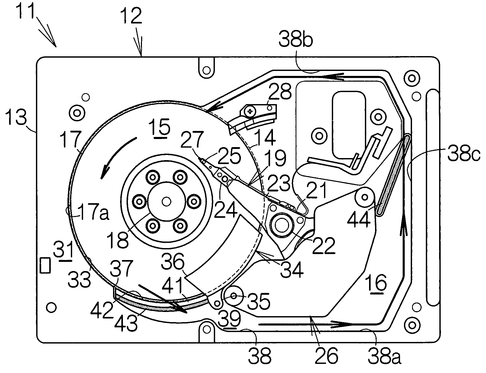
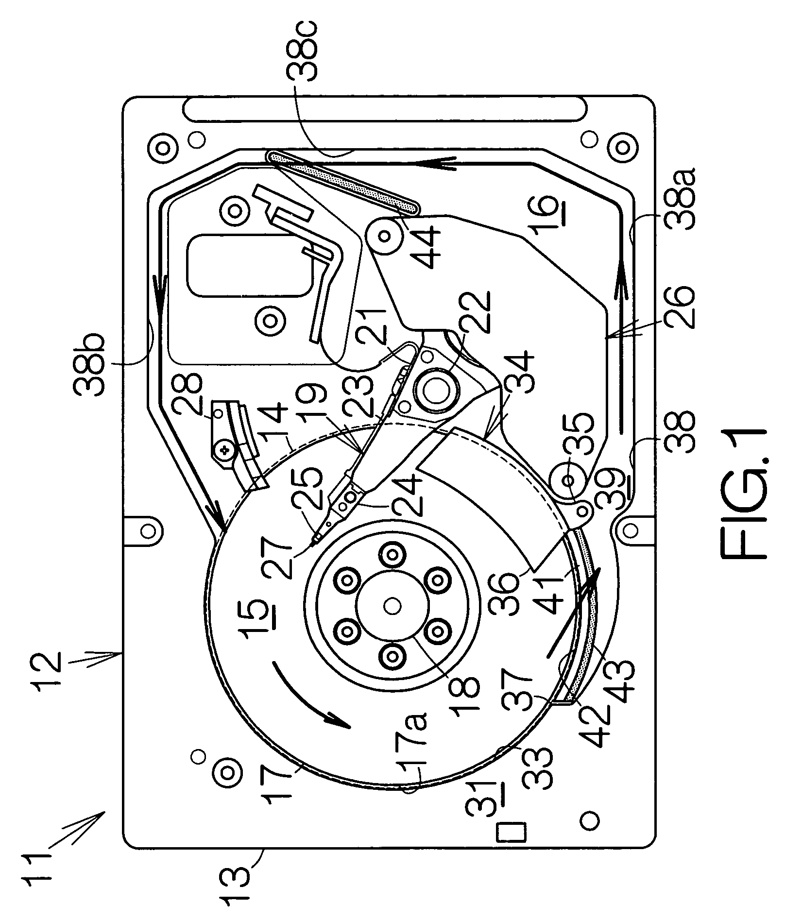
[0023]FIG. 1 schematically illustrates the inner structure of a hard disk drive (HDD) 11 as an example of a disk drive or storage device according to an embodiment of the present invention. The hard disk drive 11 includes a box-shaped enclosure 12. The size of the enclosure 12 is set for a magnetic recording disk of the 3.5 inches diameter type, for example. The enclosure 12 includes a boxed-shaped base 13 defining an inner space, for example. The base 13 may be made of a metallic material such as aluminum, for example. Casting process may be employed to form the base 13. A cover, not shown, is coupled to the base 13. The cover closes the opening of the inner space within the base 13. Pressing process may be employed to form the cover out of a plate material, for example.

[0024]A disk space 15 and an actuator space 16 are defined in the base 13. The disk space 15 is contoured with an imaginary cylinder 14. The actuator space 15 located adjacent the imaginary cylinder 14. The inner sp...


PUM

PropertyMeasurementUnit
diameteraaaaaaaaaa
diameteraaaaaaaaaa
current velocityaaaaaaaaaa

Abstract

First and second shroud surfaces are defined along an imaginary cylinder coaxial to a recording disk. A shroud plate is located between the first and second shroud surfaces. Airflow flows outward along the surface of the rotating recording disk based on the centrifugal force. The shroud plate serves to establish the continuity of the first and second shroud surfaces. The first and second shroud surfaces and the shroud plate serve to reliably suppress turbulence of the airflow. Vibration of the recording disk is suppressed than ever. An inflow opening is located in a space between the first and second shroud surfaces. The rectifier plate is located downstream of the inflow opening. The rectifier plate serves to direct the airflow flowing along the first shroud surface to the inflow opening. A larger amount of airflow can be introduced into the inflow opening. A dust catcher receives airflow of a sufficient amount.

Description

BACKGROUND OF THE INVENTION[0001]1. Field of the Invention[0002]The present invention relates to a recording disk drive such as a hard disk drive, HDD. In particular, the invention relates to a recording disk drive comprising a recording disk and a shroud surface designed to face the outward peripheral surface of the recording disk at a certain constant interval.[0003]The terms “upstream” and “downstream” are defined based on the direction of rotation of a recording disk or magnetic recording disk in this specification.[0004]2. Description of the Prior Art[0005]A hard disk drive, HDD, allows disposition of a shroud at a location outside a magnetic recording disk. The shroud defines a shroud surface opposed to an outward peripheral surface of the magnetic recording disk at a certain constant interval. A land is located outside the magnetic recording disk at a position downstream of the shroud. An inflow opening is defined between the shroud and the land. A filter is located at the in...

Claims


Application Information

Patent Timeline
Patent Type & Authority Patents(United States)
IPC IPC(8): G11B33/14
CPCG11B25/043G11B33/1446G11B33/148
Inventor SUWA, MASAYAKANEKO, HISASHIMATSUDA, YOSHIHARUSHIMIZU, KEISHI
Owner TOSHIBA STORAGE DEVICE CORP
Why Eureka
Try Eureka