
Mower deck enhancement

a mower and enhancement technology, applied in the field of new mower deck enhancement, can solve the problems of affecting the performance and intended operation of one or both modes, and unable to allow the discharge of grass clippings from the mower deck, so as to improve the flow of grass clipping, reduce air turbulence, and prevent turbulence

Inactive Publication Date: 2009-07-07
THE SHIVVERS GROUP
View PDF25 Cites 11 Cited by
  • Summary
  • Abstract
  • Description
  • Claims
  • Application Information

AI Technical Summary

Benefits of technology

[0006]Therefore it is a primary object, feature, or advantage of the present invention to improve over the state of the art.
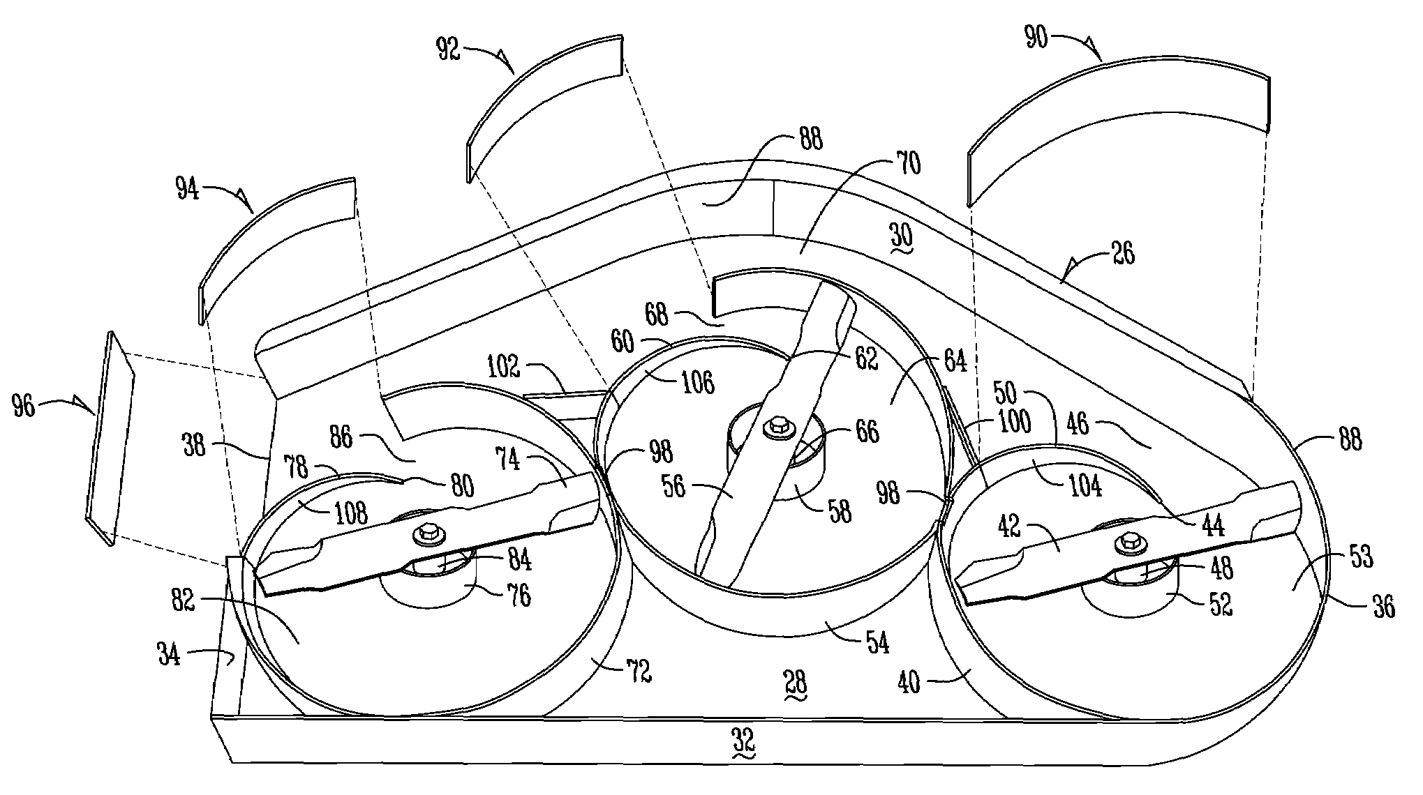
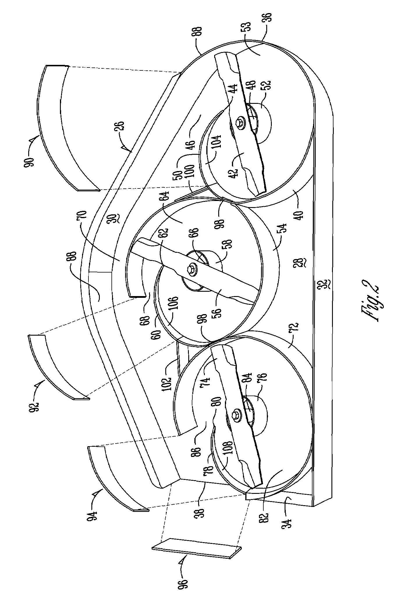
[0007]It is a further object, feature, or advantage of the present invention to provide a mower deck enhancement operating in the discharge mode wherein each blade has a wraparound baffle with a sloped wall portion terminating in the throat to enhance grass clipping flow within the baffle, throat and discharge area by preventing turbulence between blade intersection points, between and around the blades / spindles, through the throat area, and out the discharge.
[0008]Yet another object, feature, or advantage of the present invention is to provide a mower deck enhancement in the mulching operation wherein a mulching baffle may be inserted in an opening in the wraparound baffle to close off the throat area to create a full wraparound baffle around each blade to reduce the air turbulence at blade intersection points, increase the suction and overall cutting effectiveness of the blades, and reduce grass clipping volumes being transferred from one blade to any one of the other blades.
[0009]A further object, feature, or advantage of the present invention is to provide a mower deck enhancement wherein a collar is positioned around the spindle attached to the blade to prevent air flows within the baffle from stalling, creating turbulence or vortices approximate the spindle resulting in less buildup, clogging, air flow conflicts between stalled air proximate the spindle, and more transient air flows away from the spindle to encourage smooth, linear flows of grass clippings around the collar.
[0010]Yet another object, feature, or advantage of the present invention is to provide a mower deck enhancement wherein air flow streams resulting from individual blades are kept separate from each other until exiting the baffle into the throat and discharge areas of the mower deck where unidirectional air flow streams generate a high throughput out of the throat and discharge areas of the mower deck.
[0011]One or more of these and / or other objects, features, or advantages of the present invention will become apparent from the specification and claims that follow.

Problems solved by technology

Arguably, these designs still suffer from the undesirable problems of buildup, clumping, and clogging of grass clippings within the mower housing.
Mower housings are predisposed to these problems in large part as a result of stalled or non-unidirectional air flow streams within the mower housing and air turbulence generated at blade intersection points.
A full wraparound baffle would prevent turbulence at blade intersection points and where air flow streams traveling in counter directions between the various sets of blades collide to disrupt the overall suspension and discharge of clippings, but would not allow discharge of grass clippings from the mower deck.
The space proximate the spindle, between the blade and top wall, is predisposed to vortices, stalling and disruption of air flow streams, which causes grass clipping buildup.
Stalled air streams around the spindle contribute to airflow boundary problems between the stalled air streams near the spindle and more fluid air streams farther away from the spindle.
Although these mowers allow the user to quickly switch between side discharge and mulching, the baffles used to complete the conversion fail to optimize the full potential of both modes and in fact, often hinder the performance and intended operation of one or both of these modes due to inadequate considerations given to turbulence issues, such as air flow conflicts between blades, at blade intersection points or around the blade / spindle.

Method used


Image

  • Mower deck enhancement
  • Mower deck enhancement
  • Mower deck enhancement

Examples


Embodiment Construction

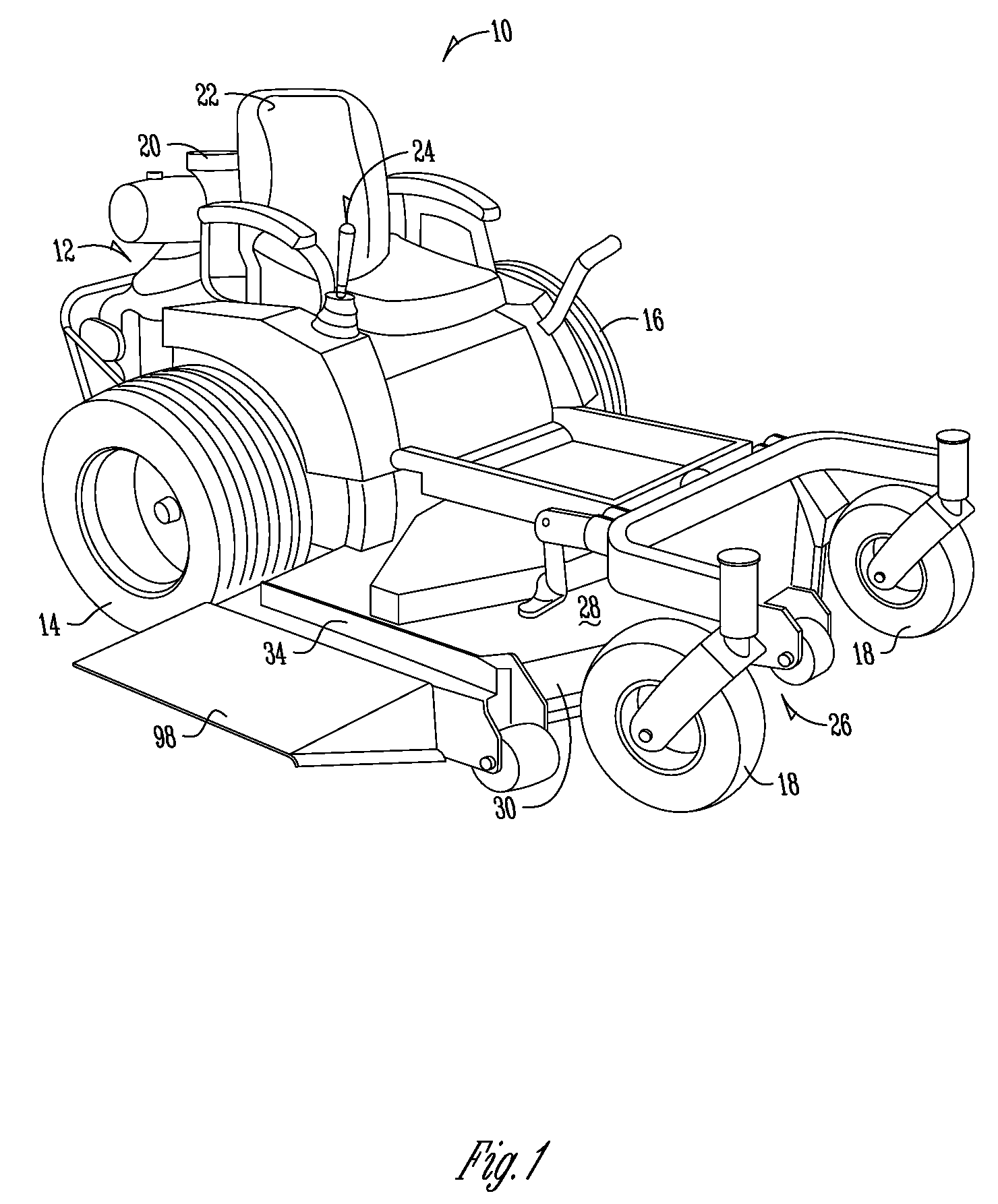
[0045]The numeral 10 refers to a multiblade lawn mower upon which the invention herein is mounted. Lawn mower 10 is shown to be a riding lawn mower, but it could also be a walk-behind or pull-type lawn mower. Lawn mower 10 generally includes a frame 12 having a pair of driven wheels 14 and 16 at the rear end thereof and at least one or more castor wheels 18 at the forward end thereof. Lawn mower 10 also includes a conventional power means, such as an internal combustion engine 20 for driving the wheels 14 and 16 for driving the cutting blades, as will be described hereinafter. An operator's station 22 is provided on frame 12 to accommodate an operator. Controls 24 are also provided for operating the lawn mower 10.

[0046]Mower deck 26 is mounted on the forward end of frame 12. Mower deck 26 includes a top wall 28, a front wall 30, a back wall 32, first side wall 34 and second side wall 36 defining a downwardly directed interior opening. In the embodiments shown in the drawing, first s...


PUM


Abstract

A multiblade lawn mower has a mower deck with a downwardly directed interior opening. At least two rotary blades are disposed within the opening. A generally circular wraparound baffle is adapted to surround each rotary blade. The wraparound baffle has a throat area opening generally towards one of the walls at an acute angle and / or an opening in the mower deck. The wraparound baffle also has a sloped wall portion adapted to decrease in height gradually from the height of the wraparound baffle to an edge terminating in the throat area. A collar is attached to the top wall and extends downward to a position adjacent the rotary blade. The collar surrounds a spindle attached to the rotary blade to prevent grass buildup created by movement of the rotary blades in a vortex area proximate the spindle.

Description

FIELD OF THE INVENTION[0001]The present invention relates to a new mower deck enhancement and more particularly a mower deck enhancement having a wraparound baffle for each blade with a sloped wall portion terminating in the throat area for discharge operation and a mulching baffle positioned in the throat area to fully enclose the wraparound baffle for mulching operation.BACKGROUND OF THE INVENTION[0002]Traditionally, mower decks consist of front and rear baffles designed to create a smooth flow of grass cuttings suspended in air flow streams created by the blades within the mower housing, through the throat area and out the discharge. Arguably, these designs still suffer from the undesirable problems of buildup, clumping, and clogging of grass clippings within the mower housing. Mower housings are predisposed to these problems in large part as a result of stalled or non-unidirectional air flow streams within the mower housing and air turbulence generated at blade intersection poin...

Claims


Application Information

Patent Timeline
Patent Type & Authority Patents(United States)
IPC IPC(8): A01D67/00
CPCA01D34/71
Inventor SCHICK, SCOTT A.THATCHER, STEPHEN C.
Owner THE SHIVVERS GROUP
Learn More