Muffler duct

a muffler duct and duct technology, applied in the field of ducts, can solve the problems of difficult mounting of the muffler duct on a vehicle or the like, uncomfortable user feel of low frequency, etc., and achieve the effect of reducing the noise of low frequency

Inactive Publication Date: 2009-07-07
TOYODA GOSEI CO LTD
View PDF16 Cites 10 Cited by
  • Summary
  • Abstract
  • Description
  • Claims
  • Application Information

AI Technical Summary

Benefits of technology

[0009]The invention has been conceived in view of the background thus far described, and has an object to provide a muffler duct, which can reduce the noises of a low frequency without needing any long communicating tube and can reduce the noises of the low frequency over a wide range.
[0015]Moreover, the muffler duct of the invention can reduce the noises of a low frequency over a wide range. The reason for this reduction is not defined but seems to have some relation to the facts that the muffler duct of the invention does not have any communicating tube, and that the inside of the duct body and the inside of the resonance box communicate directly with each other.
[0016]In the muffler duct of the invention, the gas vent opening of the through hole shape is formed in the partition wall of the resonance box. As a result, the inside and the outside of the resonance box communicate with each other through the gas vent opening. In the muffler duct of the invention, therefore, the sound pressure inside of the resonance box becomes lower. Therefore, the anti-resonance phenomenon can be suppressed. Moreover, the communication opening is covered with the gas-permeable member. Since the gas vent opening is covered with the gas-permeable member, the noises, which might otherwise leak out from the inside of the resonance box, are reduced.
[0018]In the muffler duct of the invention, moreover, the gas vent opening portion composed of the gas vent opening and the gas-permeable member is formed in the partition wall at a position to confront the communication opening. The communication opening is either the joint portion between the partition wall and the circumferential wall or the portion, which is formed in the circumferential wall and provides the communication between the inside of the duct body and the inside of the resonance box. The gas vent opening portion is formed in the partition wall at the position to confront the communication opening, so that the noises having propagated from the duct body to the resonance box easily reach the gas vent opening easily. Thus, the muffler duct of the invention can suppress the anti-resonance phenomenon more reliably.
[0019]Like the muffler duct introduced by JP-A-5-163925, specifically, the muffler duct of the invention has the opening (i.e., the gas vent opening portion) for providing the communication between the inside and the outside of the resonance box. Unlike the muffler duct introduced by JP-A-5-163925, however, the gas vent opening portion in the muffler duct of the invention contributes not to the tuning of the resonance frequency F but to the reduction of the anti-resonance phenomenon and the reliable reduction of the noises.
[0020]The muffler duct of the invention having the aforementioned (1) can shorten the distance between the communication opening and the gas vent opening portion. Therefore, it is possible to make the anti-resonance phenomenon less and to reduce the noises more reliably.

Problems solved by technology

Here, it is widely known that mainly the noises of the low frequency make the user feel uncomfortable.
This raises a problem to make it difficult to mount the muffler duct on a vehicle or the like.

Method used


Image

  • Muffler duct
  • Muffler duct
  • Muffler duct

Examples


embodiment

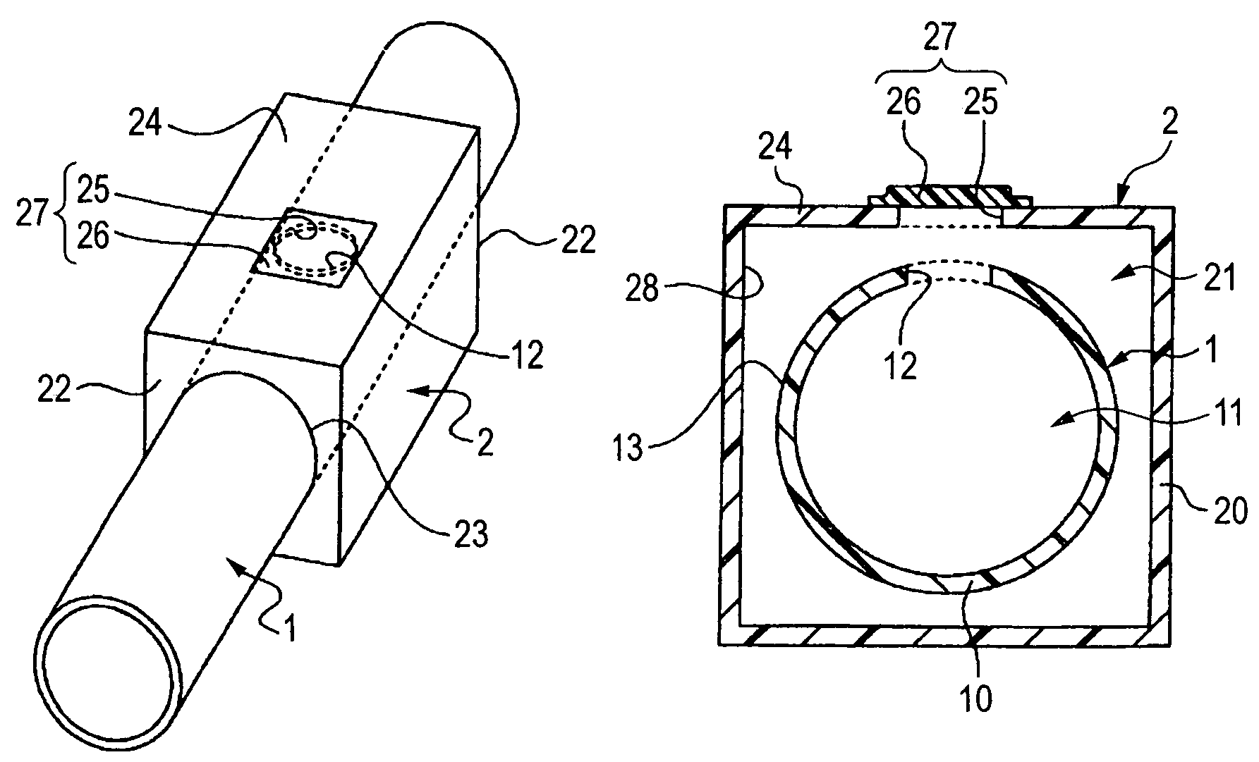
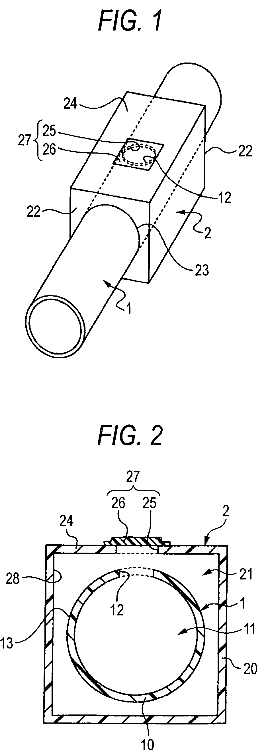
[0039]The muffler duct of the embodiment is provided with the aforementioned (1) and (2). A perspective view expressing the muffler duct of the embodiment schematically is shown in FIG. 1. On the other hand, FIG. 2 is a sectional view schematically showing the behavior, in which the muffler duct of the embodiment is cut in parallel with the radial direction of the duct body.

[0040]As shown in FIGS. 1 and 2, the muffler duct of the embodiment includes a duct body 1 and a resonance box 2. The duct body 1 has a generally cylindrical shape. The inside and the outside of the duct body 1 are partitioned by a circumferential wall 10. The resonance box 2 has a generally rectangular box shape. The inside and the outside of the resonance box 2 are partitioned by a partition wall 20.

[0041]The duct body 1 has its axial portion housed along the longitudinal direction of the resonance box 2 in the inside 21 of the resonance box 2. In a pair of partitioning side walls 22 as positioned at the longit...


PUM


Abstract

In a muffler duct including a duct body and a resonance box, the inside of the duct body and the inside of the resonance box are made to communicate directly with each other not through a cylindrical member. In the partition wall of the resonance box, a gas vent opening portion, which is composed of a gas vent opening having a through hole shape and a gas-permeable member having a gas vent passage of a labyrinth shape for covering said gas vent opening, is formed at a position to confront a communication opening, through which the inside of the duct body and the inside of the resonance box communicate with each other.

Description

BACKGROUND OF THE INVENTION[0001]1. Field of the Invention[0002]The present invention relates to a duct, which can be used as the intake pipe of an internal combustion engine, for example.[0003]2. Related Art[0004]The muffler duct is used as an intake pipe or an exhaust pipe of an internal combustion engine or an air-conditioning apparatus. This muffler duct reduces the propagation sounds to propagate from a noise source such as the internal combustion engine or the air-conditioning apparatus, or the noises which are caused by its own intake pulsations. As the known muffler duct (as referred to JP-A-5-163925, for example), a muffling device (e.g., the so-called “Helmholtz resonator”), which is composed of a box-shaped resonance box and a cylindrical member (or a communicating tube), is connected to a cylindrical duct body.[0005]In the muffler duct of this kind, the muffling device resonates with a predetermined frequency component (or a resonance frequency F) of the noises thereby t...

Claims


Application Information

Patent Timeline
Patent Type & Authority Patents(United States)
IPC IPC(8): F01N1/02F01N1/22F02M35/10F01N1/00
CPCF01N1/023F02M35/1255F02M35/1238G10K11/172
Inventor IDO, YASUSHIHATTORI, MASARU
Owner TOYODA GOSEI CO LTD
Why Eureka
Try Eureka