Side air bag with a controlled opening of a pressure equalization chamber

a technology of pressure equalization chamber and air bag, which is applied in the direction of pedestrian/occupant safety arrangement, vehicular safety arrangments, vehicle components, etc., can solve problems such as demand-driven connection failures

Inactive Publication Date: 2009-07-07
AUTOLIV DEV AB
View PDF12 Cites 11 Cited by
  • Summary
  • Abstract
  • Description
  • Claims
  • Application Information

AI Technical Summary

Benefits of technology

[0007]In its basic concept, the present invention provides at least the one pressure equalization chamber equipped across its surface with additionally provided connections of the fabric layers of the air bag in such a manner, that the gas stream entering the pressure equalization chamber after the inflation of the immediately inflatable primary chamber inflates portions of the pressure equalization chamber as a function of the applied pressure by separation of the additional connections. The invention has the advantage that at least the one pressure equalization chamber automatically provides an adapted volume as a function of the pressure conditions being generated in the air bag, which volume is filled by the displaced gas. It is thus possible to limit the elasticity of the primary chambers, which are stressed by the impact of the occupants, to the desired degree, without complicated controls with additional control means for the adjustment of the gas transfer into the pressure equalization chamber being required.

Problems solved by technology

In this example of an embodiment, the gas moving into the pressure equalization chamber can initially fill the spaces between the individual point-shaped connections; to the extent that this is not enough, the correspondingly increasing interior pressure leads to a demand-driven failure of the connections, so that increasingly an inflation volume in the pressure equalization chamber is made available.

Method used


Image

  • Side air bag with a controlled opening of a pressure equalization chamber
  • Side air bag with a controlled opening of a pressure equalization chamber
  • Side air bag with a controlled opening of a pressure equalization chamber

Examples


Embodiment Construction

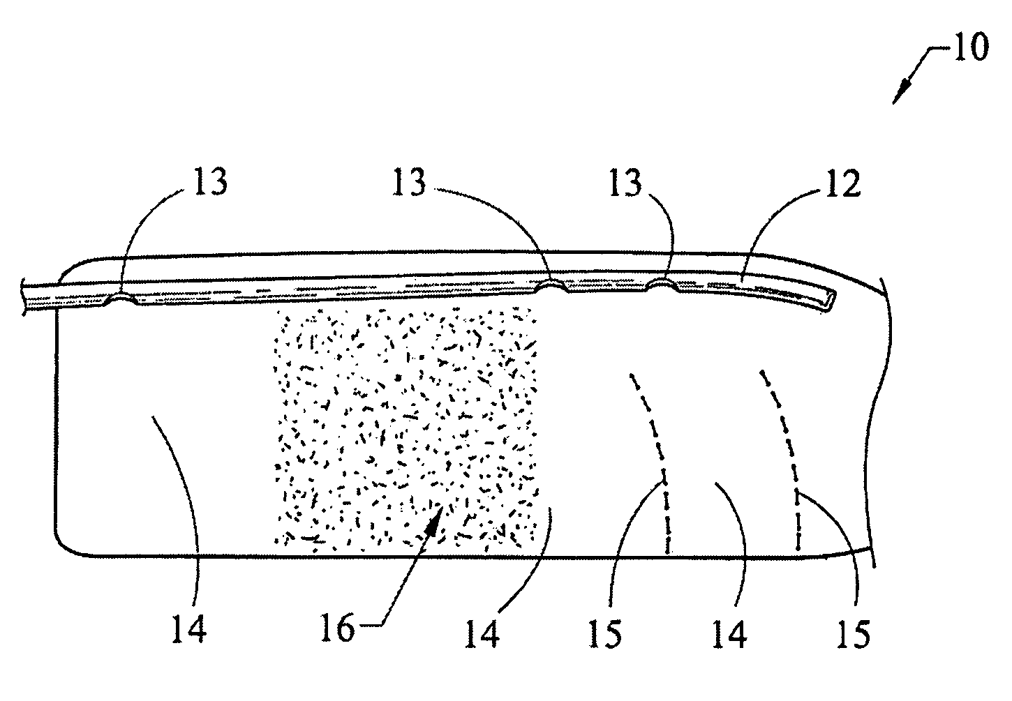
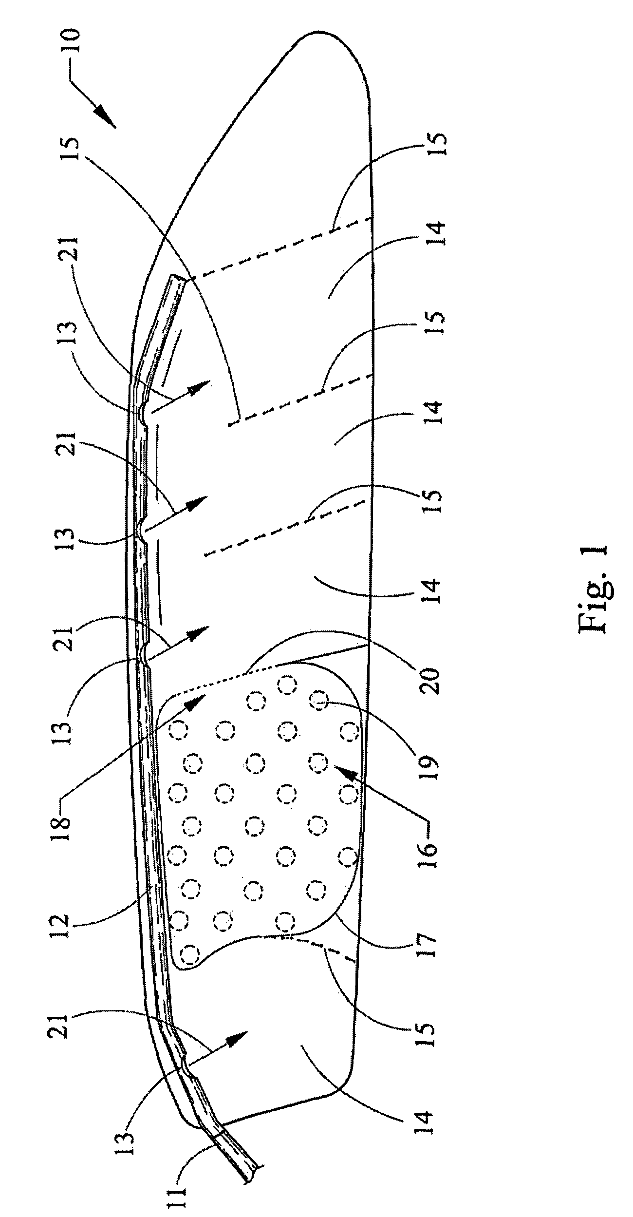
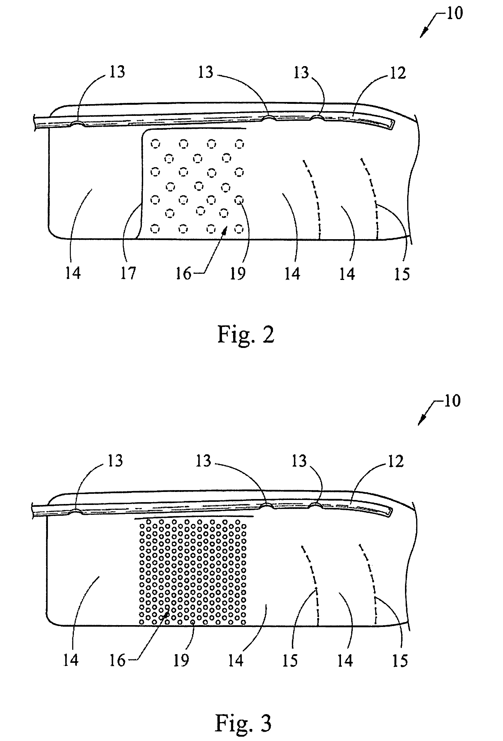
[0019]The air bag 10 shown in FIG. 1 has an overall elongated form, with the air bag 10 in the unfolded condition shown is, for example, stretched out between the A-pillar and the C-pillar of a motor vehicle, so as to cover the side windows of the vehicle to provide head protection against a lateral impact. Insofar as the air bag 10 is placed in the roof frame of the motor vehicle in the folded-up state before it is triggered, an inflatable tube 12 is located in this region at the upper edge of the air bag 10, which tube is connected at its back end to a gas generator 11, which is located in the motor vehicle.

[0020]According to the desired protective effect, the air bag 10 is subdivided into several primary chambers 14 by several subdivisions 15, which can, for example, be constructed as strong sewed seams, in the process of which the individual primary chambers 14 are each provided with openings 13 in the inflation tube 12, so that, when the gas generator 11 is triggered, these cha...


PUM


Abstract

A side-impact air bag system for motor vehicles with an air bag (10) extending across at least a part of the longitudinal extent of the vehicle. The air bag (10) is formed by two layers of fabric which are joined to each other and is located in the region of the roof frame of the vehicle in its folded state, before it is unfolded in the form of a curtain. An inflation device (11) releases an inflating gas, and the air bag (10) contains at least one primary chamber (14) which can be inflated by directly feeding gas into it, as well as at least one additional pressure equalization chamber (16), which is separated from the immediately inflatable primary chamber (14). The pressure equalization chamber (16) is equipped across its surface with additionally placed connections (19) of the fabric layers of the air bag (10) in such a manner that the gas stream entering the pressure equalization chamber (16) after inflation of the directly inflatable primary chamber (14) as a function of the pressure acting upon it, inflates portions of the pressure equalization chamber (16) by separation of the additional connections (19).

Description

CROSS REFERENCE TO RELATED APPLICATION[0001]This application claims priority to PCT / EP2006 / 000938, filed Feb. 3, 2006.FIELD OF THE INVENTION[0002]The invention concerns a side-impact occupant protection system for motor vehicles with an air bag extending across at least a part of the longitudinal extent of the vehicle, in which the air bag, which is formed by two layers of fabric, which are joined to each other, is located in the region of the roof frame of the vehicle in a folded-up condition. The air bag unfolds in the form of a curtain and is connected to an inflation device which releases an inflation gas. The air bag contains at least one primary chamber, which can be inflated by directly feeding gas into it, as well as at least one additional pressure equalization chamber, which is separated from the immediately inflatable primary chamber.BACKGROUND OF THE INVENTION[0003]A side-impact protective system with the above-mentioned general characteristics is described in U.S. Pat. ...

Claims


Application Information

Patent Timeline
Patent Type & Authority Patents(United States)
IPC IPC(8): B60R21/213B60R21/233B60R21/232B60R21/2342
CPCB60R21/232B60R2021/23316B60R21/2342
Inventor ZAURITZ, RALFISENSEE, THOMAS
Owner AUTOLIV DEV AB
Why Eureka
Try Eureka