Bidirectional optical assembly and method for manufacturing the same

a technology of bidirectional optical assembly and manufacturing method, which is applied in the direction of optical elements, multiplex communication, instruments, etc., can solve the problems of difficult miniaturization of optical assembly types and relatively uneconomical costs, and achieve the effect of superior optical coupling efficiency

Active Publication Date: 2009-07-07
SUMITOMO ELECTRIC IND LTD
View PDF8 Cites 28 Cited by
  • Summary
  • Abstract
  • Description
  • Claims
  • Application Information

AI Technical Summary

Benefits of technology

[0009]The first TOSA and the ROSA are preferable to provide wavelength selective filters to selectively transmit light with first and third wavelengths, respectively, which enables to reduce the optical noise.
[0010]Further, it is preferable to provide an isolator between the first and second WDM filters to transmit light propagating from the first WDM filter to the second WDM filter and to cut light propagating from the second WDM filter to the first WDM filter, which prevent light emitted from the optical fiber from returning the first and second TOSAs to become a noise source for the light-emitting devices installed within the first and second TOSAs.
[0012]Another aspect of the present invention relates to a method for manufacturing the bi-directional optical assembly. In the present method, first of all, the first TOSA permanently fixes in the position thereof by the YAG laser welding after aligning with the sleeve assembly via the inner housing. The first TOSA optically aligns with the inner housing along the direction parallel to the optical axis, while, the sleeve assembly optically aligns with the inner housing along directions perpendicular to the optical axis. Next, the second TOSA optically aligns with the outer housing along the direction parallel to the optical axis, while, the outer housing optically aligns with the inner housing along directions perpendicular to the optical axis. Thus, the first and second TOSAs may be aligned independently and separately along three directions against the optical axis, which attains a superior optical coupling efficiency.
[0014]Moreover, by securing the ROSA to the inner housing through the second alignment member, the ROSA may be aligned not only in two directions perpendicular to the optical axis but also in the direction parallel to the optical axis. Accordingly, the superior optical coupling efficiency may be attained for the ROSA.

Problems solved by technology

This type of the optical assembly is hard to miniaturize and is relatively cost un-effective because the assembly requires a number of optical element, for instance, the optical filter and the optical coupler.

Method used


Image

  • Bidirectional optical assembly and method for manufacturing the same
  • Bidirectional optical assembly and method for manufacturing the same
  • Bidirectional optical assembly and method for manufacturing the same

Examples


first embodiment

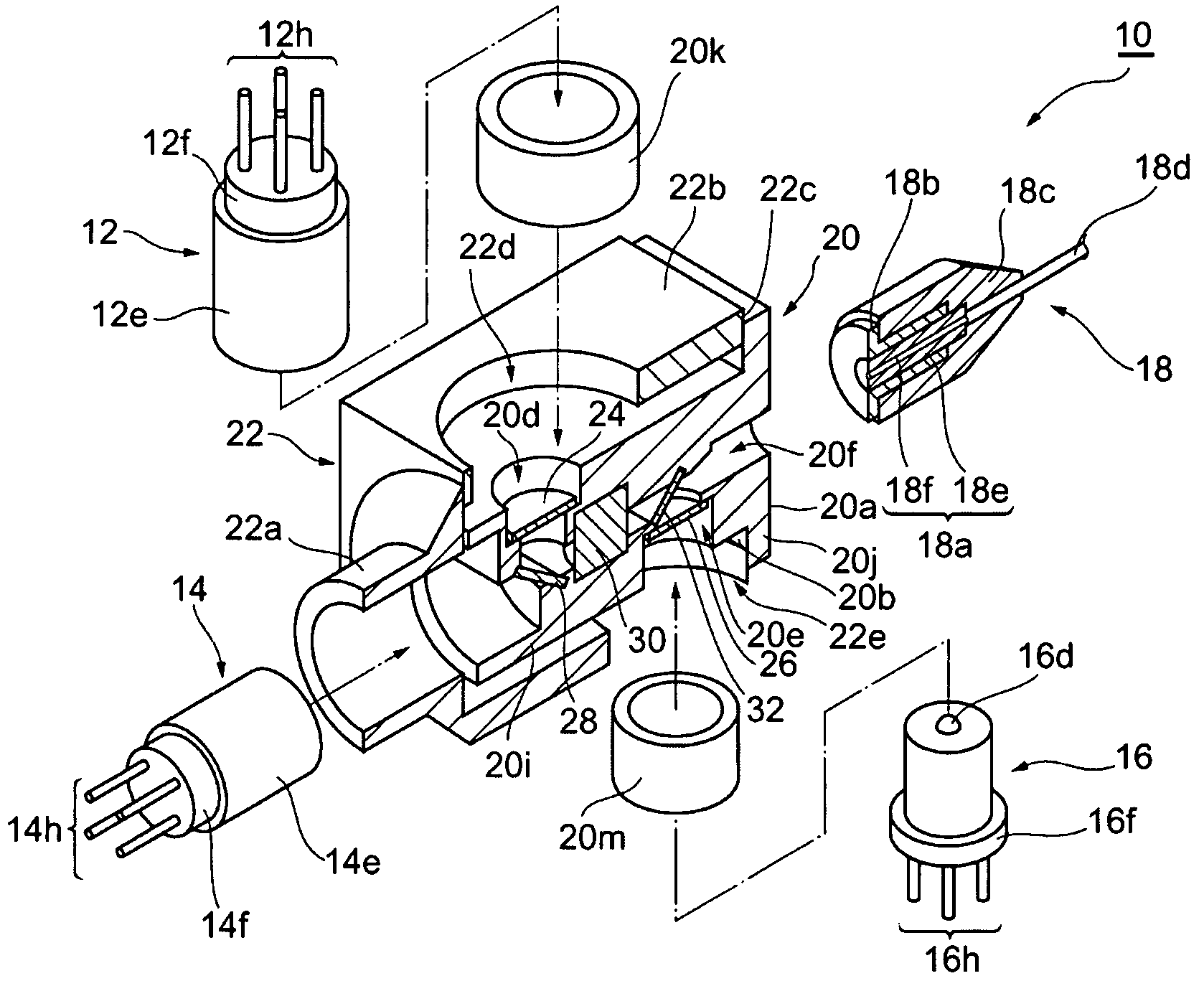
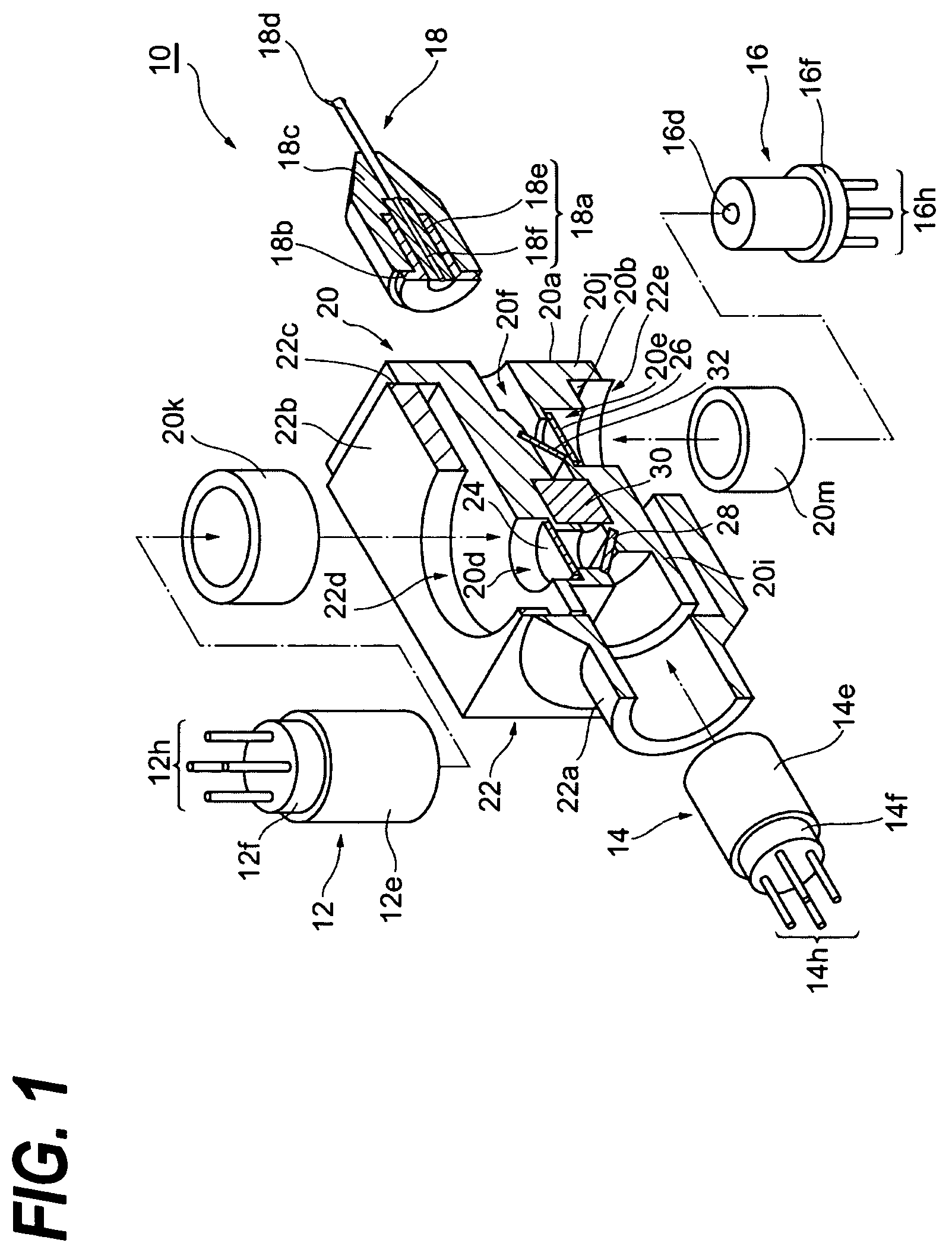
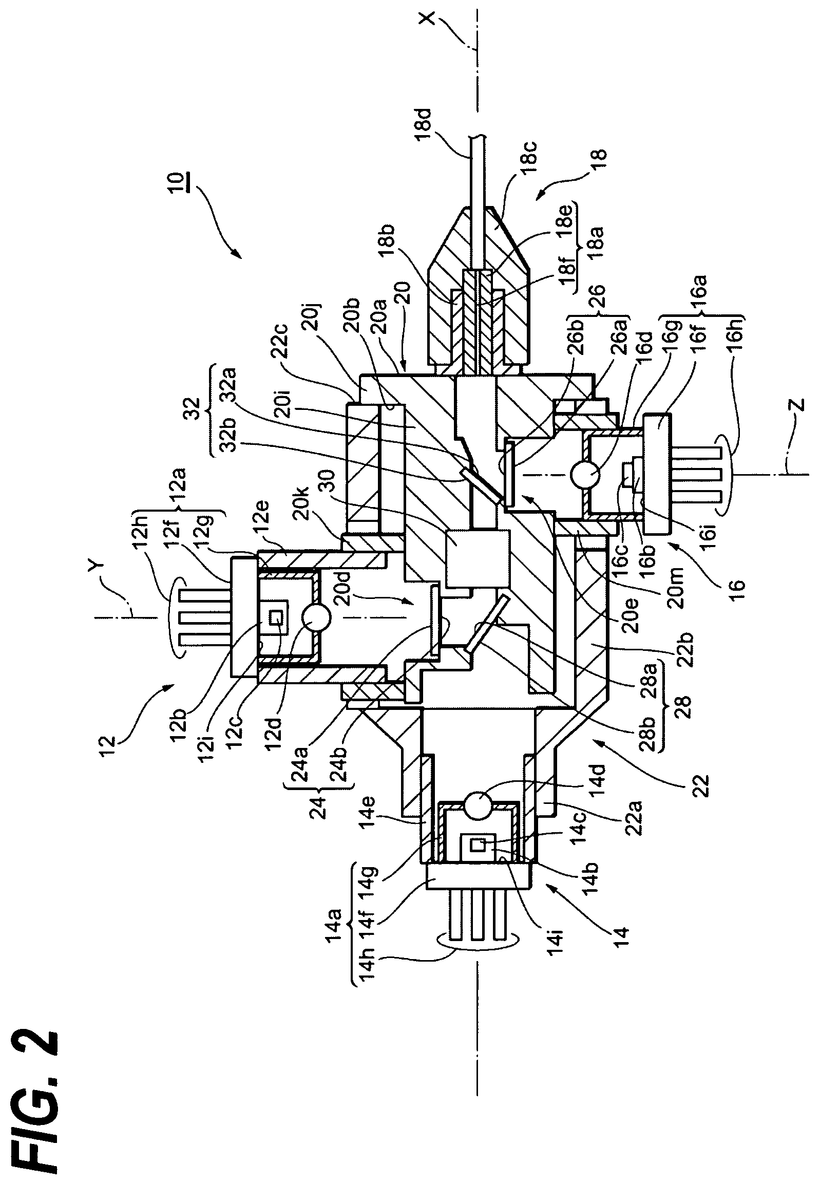
[0021]FIG. 1 is an exploded perspective view showing a bidirectional optical assembly according to the first embodiment of the present invention, which is partially broken. FIG. 2 is a cross sectional view of the bidirectional optical assembly according to the first embodiment. The bidirectional optical assembly 10 shown in FIGS. 1 and 2 comprises a first transmitting optical subassembly (TOSA) 12, a second TOSA 14, a receiving optical subassembly (ROSA) 16, a sleeve assembly 18, an inner housing 20 and an outer housing 22.

[0022]The first TOSA 12 comprises a package 12a, a sub-mount 12b, a light-emitting device 12c, a condenser lens 12d, and a sleeve 12e. The package 12a includes a stem 12f, a lens cap 12g, and a lead terminal 12h. The stem 12f provides a mounting surface 12i. A plurality of lead terminals 12h extend from the stem 12g to a direction substantially perpendicular to the stem 12f. On the mounting surface 12i is installed with the sub-mount 12b, and on the sub-mount 12b ...

second embodiment

[0045]FIG. 3 is a cross sectional view of the second embodiment of the bi-directional optical assembly according to the present invention. Next, regarding the bi-directional optical assembly 10b shown in FIG. 3, configurations different from those of the bi-directional optical assembly 10 already described will be described.

[0046]In the bi-directional optical assembly lOb, the ROSA 16 further provides the sleeve 16j. This sleeve 16h has a tubular shape with one end thereof being secured by the mounting surface 16i, while, the other end thereof facing the end of the second alignment member 20m. The inner diameter of the second alignment member 20m is slightly greater than the outer diameter of the lens cap 16g.

[0047]According to this bi-directional optical assembly, the ROSA 16 may adjust the position along two directions each intersecting the axis Z by sliding the end surface of the sleeve 16j on the end surface of the second alignment member 20m. Accordingly, the optical coupling ...


PUM


Abstract

The present invention provides a bi-direction optical assembly with two optical transmitting channels by a small-sized package and relatively low cost. In the bi-directional optical assembly, the first transmitting optical subassembly (TOSA) and the receiving optical subassembly (ROSA) are optically coupled with the optical fiber via the inner housing. While the second transmitting optical subassembly is optically coupled with the optical fiber via the outer housing slidable to the inner housing.

Description

BACKGROUND OF THE INVENTION[0001]1. Field of the Invention[0002]The present invention relates to a bidirectional optical assembly, in particular, the invention relates to a bidirectional optical assembly having two ports for an optical transmitter.[0003]2. Related Prior Art[0004]A bidirectional optical assembly comprises an optical transmitting subassembly (hereinafter referred by TOSA) for a transmitting channel, an optical receiving subassembly (hereinafter referred by ROSA) for a receiving channel, an optical fiber and a housing. The housing forms a tubular shape, one end of which secures the TOSA that is arranged along an axis of the tube, while, the other end thereof secures the optical fiber to optically couple with the TOSA in precise. On the other hand, the ROSA is supported in the side of the tubular housing and coupled with the optical fiber via an optical filter. Refer to Japanese patent application published as JP-2003-524789A.[0005]It is known that one type of the bidir...

Claims


Application Information

Patent Timeline
Patent Type & Authority Patents(United States)
IPC IPC(8): G02B6/36H04J14/02
CPCG02B6/4246
Inventor NAKANISHI, HIROMIFURUMAI, MASAKI
Owner SUMITOMO ELECTRIC IND LTD
Why Eureka
Try Eureka