Techniques for reducing optical noise in metrology systems

a metrology system and optical noise technology, applied in the field of optical devices, can solve the problems of light scattering away from its intended path, scattering and distortion becoming increasingly problematic, and potential sources of optical scattering and distortion, so as to improve the performance of metrology instruments, improve the performance of metrology systems, and reduce scattering light

Inactive Publication Date: 2007-05-31
THERMA WAVE INC
View PDF10 Cites 8 Cited by
  • Summary
  • Abstract
  • Description
  • Claims
  • Application Information

AI Technical Summary

Benefits of technology

[0020] The encircle energy is used to define a metric that is referred to as Total Surface Error or TSE. TSE is defined in terms of differences in encircled energy value between the manufactured part and an ideal diffraction-limited optical component of equal focal length and numerical aperture. In general, it has been found that mirrors constructed that meet the following two conditions produce greatly improved metrology system performance: 1) Condition one requires that: TSE≦2e0.15D where D is the included diameter of the encircled energy measurement or twice the radius f

Problems solved by technology

Each of these components is a potential source of optical scatter and distortion.
As the precision of optical metrology tools increases to match shrinking semiconductor geometries, scatter and distortion become increasingly problematic and controlling both becomes an increasingly important goal.
Optical surface errors introduce optical scatter and distortions and cause light to scatter away from its intended path.
The scattered light reduces efficiency (since it is not available on the intended path) and stray light typically interferes with intended signal detection and analysis (e.g., signal to noise).
In the prior art, surface errors are typically

Method used


Image

  • Techniques for reducing optical noise in metrology systems
  • Techniques for reducing optical noise in metrology systems
  • Techniques for reducing optical noise in metrology systems

Examples


Embodiment Construction

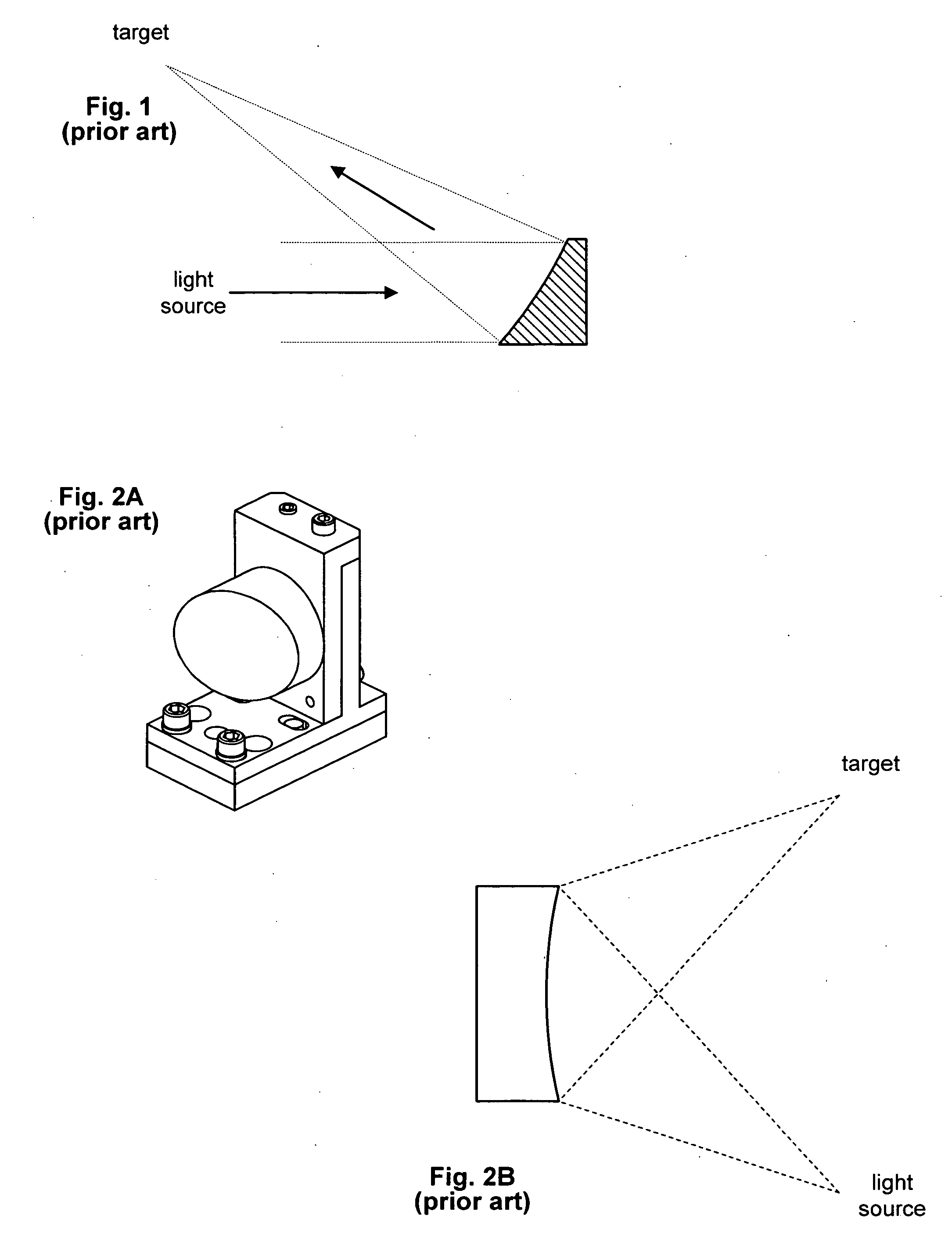
[0029] The present invention provides a method for increasing the accuracy of optical metrology tools. For this method, low scatter mirrors are produced using one of the fabrication methods discussed below. The low scatter mirrors are used in place of traditional optics to reduce optical noise. In turn, this allows measurement accuracy to be increased while maintaining or decreasing measurement spot size.

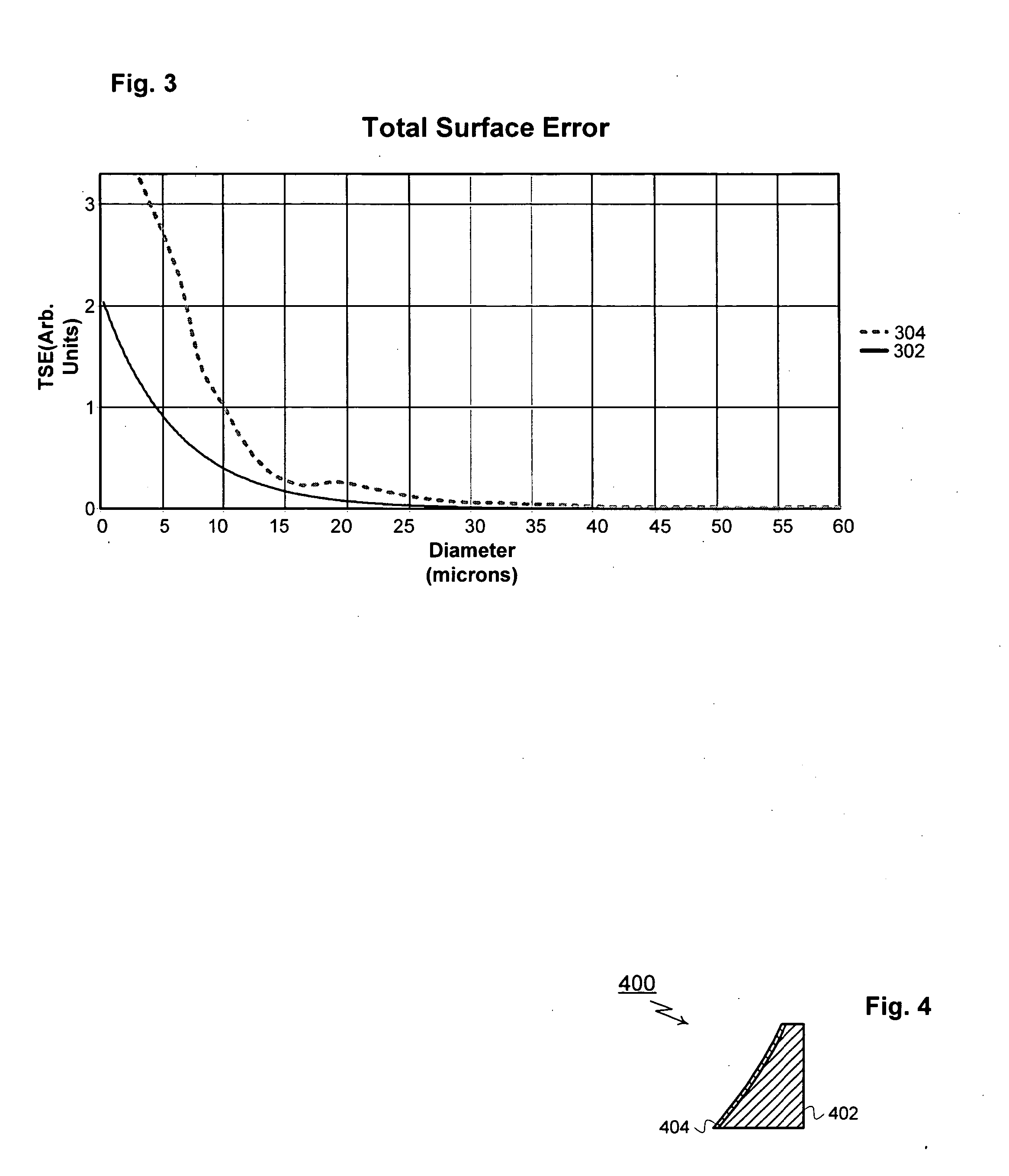
[0030] To characterize mirror quality, a measurement of encircled energy is used. In the case of an off-axis parabolic mirror, this measurement is obtained by first illuminating the mirror surface with a collimated beam. Once illuminated, the encircled energy.value (or fractional energy value) is measured at focus, and at increasingly larger distances from focus relative to an infinitely large encircled energy diameter including 100% of the incident energy. The encircle energy is used to define a metric that is referred to as Total Surface Error or TSE. TSE is defined in terms of d...


PUM


Abstract

A first method for fabricating low-noise optical components for use in optical metrology systems includes shaping a glass substrate to obtain a desire shape and then coating the glass substrate with a reflective coating. A second method includes shaping a glass master die to a desired shape and then using the glass master to form a glass substrate to the desire shape. A third method includes diamond turning a substrate to a desired shape and then polishing the substrate to meet two surface conditions which in turn ensures that the scattered light is minimized and the metrology instruments performance is greatly increased. These conditions relate to a measurement of encircled energy compared to an ideal diffraction limited component of the same focal length and diameter.

Description

PRIORITY CLAIM [0001] The present application claims priority to U.S. Provisional Patent Application Ser. No. 60 / 464,065, filed Apr. 18, 2003 the disclosure of which is incorporated in this document by reference.TECHNICAL FIELD [0002] The subject invention relates to optical devices used to non-destructively evaluate semiconductor wafers. In particular, the present invention relates to techniques for reducing optical scatter created by optical components within metrology systems. BACKGROUND OF THE INVENTION [0003] As geometries continue to shrink, manufacturers have increasingly turned to optical techniques to perform non-destructive inspection and analysis of semi-conductor wafers. The basis for these techniques is the notion that a subject may be examined by analyzing the reflected energy that results when a probe beam is directed at the subject. Ellipsometry and reflectometry are two examples of commonly used optical techniques. For the specific case of ellipsometry, changes in t...

Claims


Application Information

Patent Timeline
IPC IPC(8): G01N21/88
CPCG01N21/8806G02B5/10
Inventor HENDRIX, JAMES L.WANG, DAVID Y.
Owner THERMA WAVE INC
Why Eureka
Try Eureka