Arc lamp

a technology of arc lamps and arc lamps, which is applied in the direction of discharge tubes/lamp details, incadescent cooling arrangements, discharge tube main electrodes, etc., can solve the problems of increasing the heating of the lamp, affecting the output beam, so as to reduce the heat loss of the arc lamp, reduce the optical noise, and high energy density

Inactive Publication Date: 2001-08-14
EXCELITAS TECH
View PDF11 Cites 8 Cited by
  • Summary
  • Abstract
  • Description
  • Claims
  • Application Information

AI Technical Summary

Benefits of technology

It is a further object of this invention to provide such an improved arc lamp which dramatically reduces optical noise generated by the backscattered rearward directed radiation.
It is a further object of this invention to provide such an improved arc lamp which substantially reduces the heat loss in the arc lamp.
It is a further object of this invention to provide such an improved arc lamp which generates a high energy density, high intensity radiation beam without voids or holes.

Problems solved by technology

One shortcoming of such lamps is that more than half of the radiation generated is lost because of backscattering of the rearward directed radiation within the arc lamp.
Worse still, that lost, backscattered rearward radiation increases the heating of the lamp and contributes to optical noise that interferes with the output beam.
In some designs paraboloidal and ellipsoidal internal reflectors have been used to collect and control more of the available arc radiation but because of electrode orientation can cause a void or black hole in the direct radiation, and each of them inadvertently increases magnification at the target which in most applications is undesirable.

Method used


Image

  • Arc lamp
  • Arc lamp
  • Arc lamp

Examples


Embodiment Construction

Other objects, features and advantages will occur to those skilled in the art from the following description of a preferred embodiment and the accompanying drawings, in which:

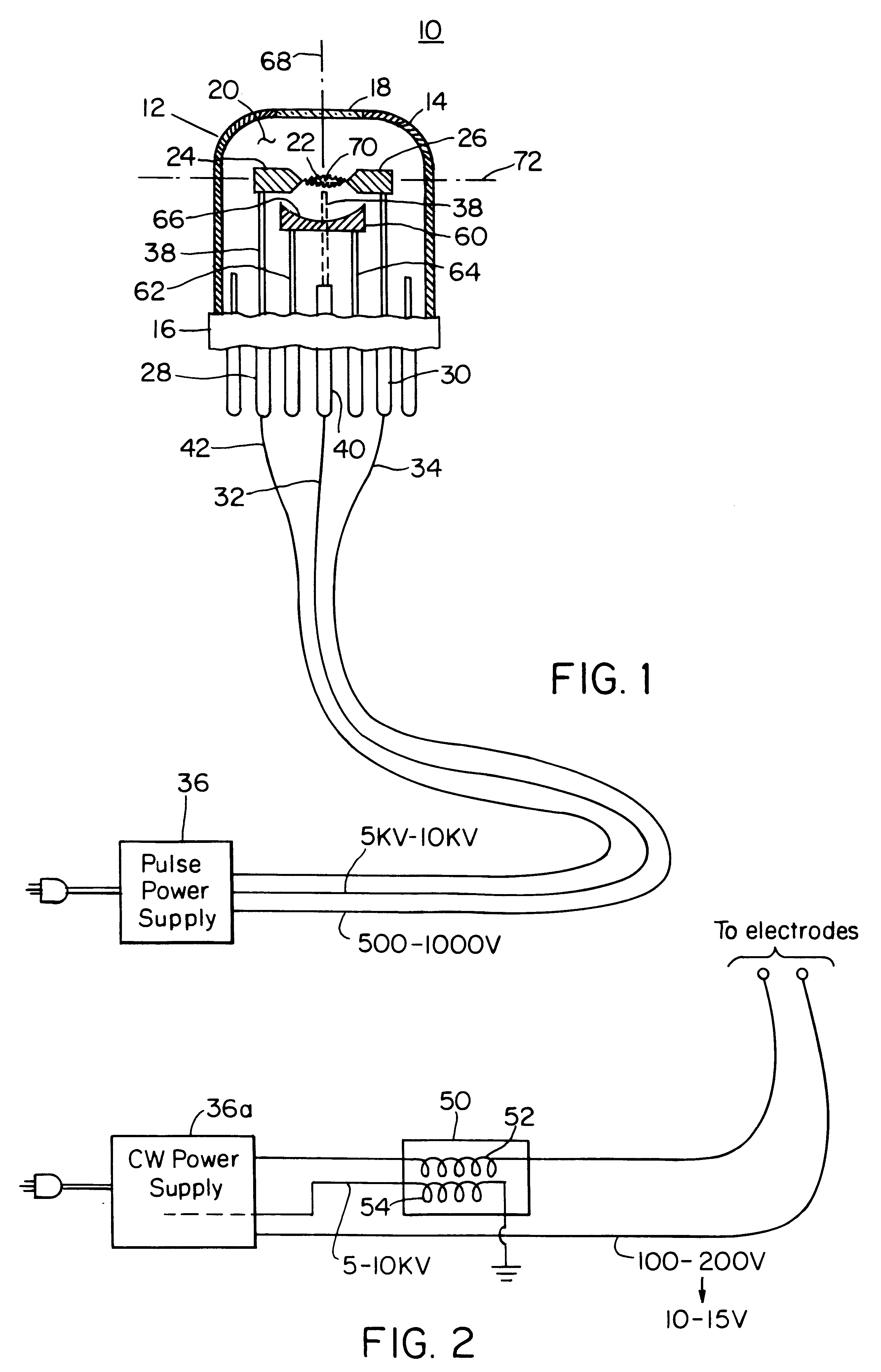
FIG. 1 is a schematic diagram of an arc lamp with pulsed power supply for operation as pulsed arc lamp employing an internal spherical reflector in accordance with the invention;

FIG. 2 is a schematic diagrammatic view of a continuous power supply for operating the arc lamp of FIG. 1 as a continuous arc lamp;

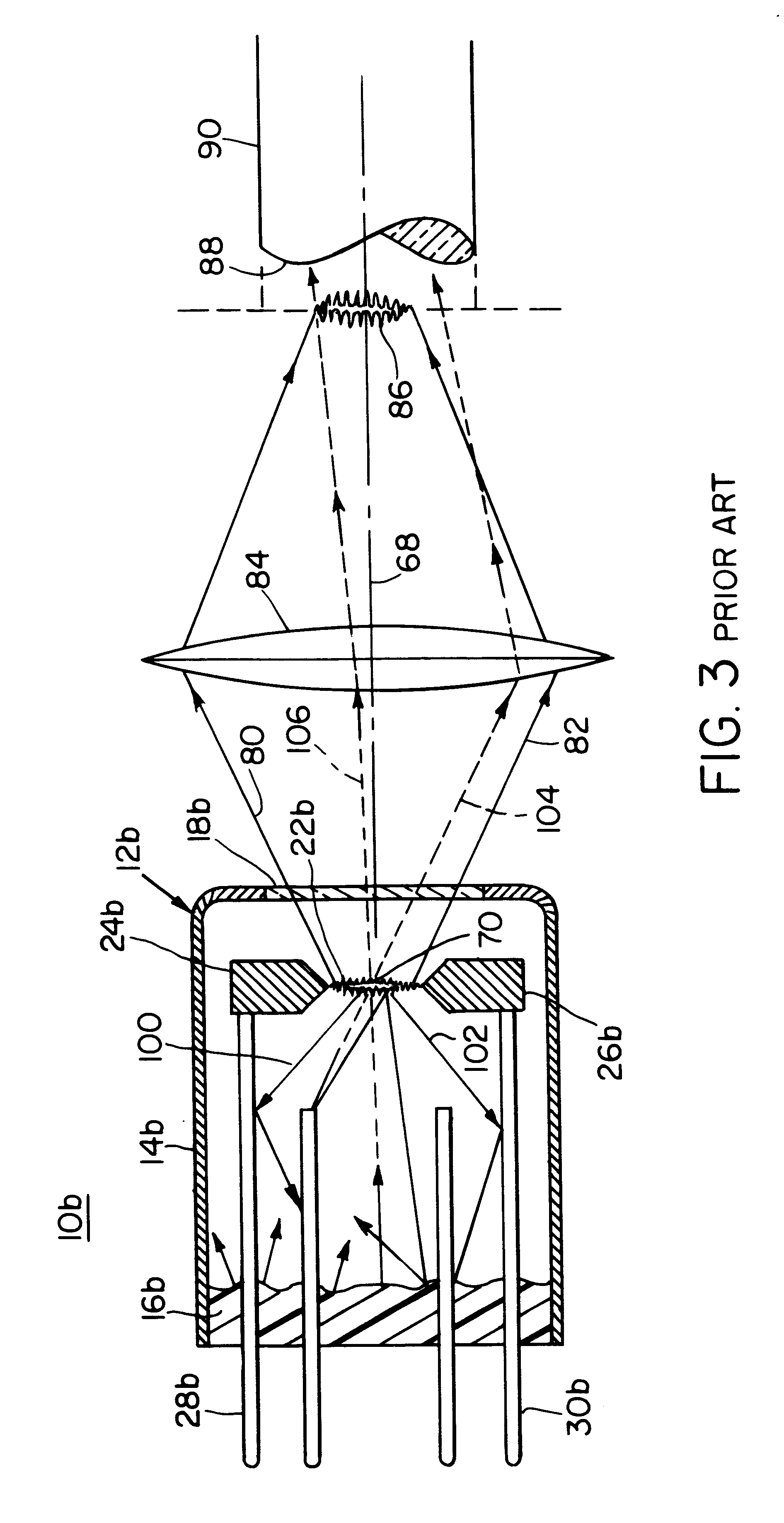
FIG. 3 is a ray diagram of a prior art arc lamp without the internal spherical reflector of this invention showing loss of rearwardly directed radiation and creation of optical noise;

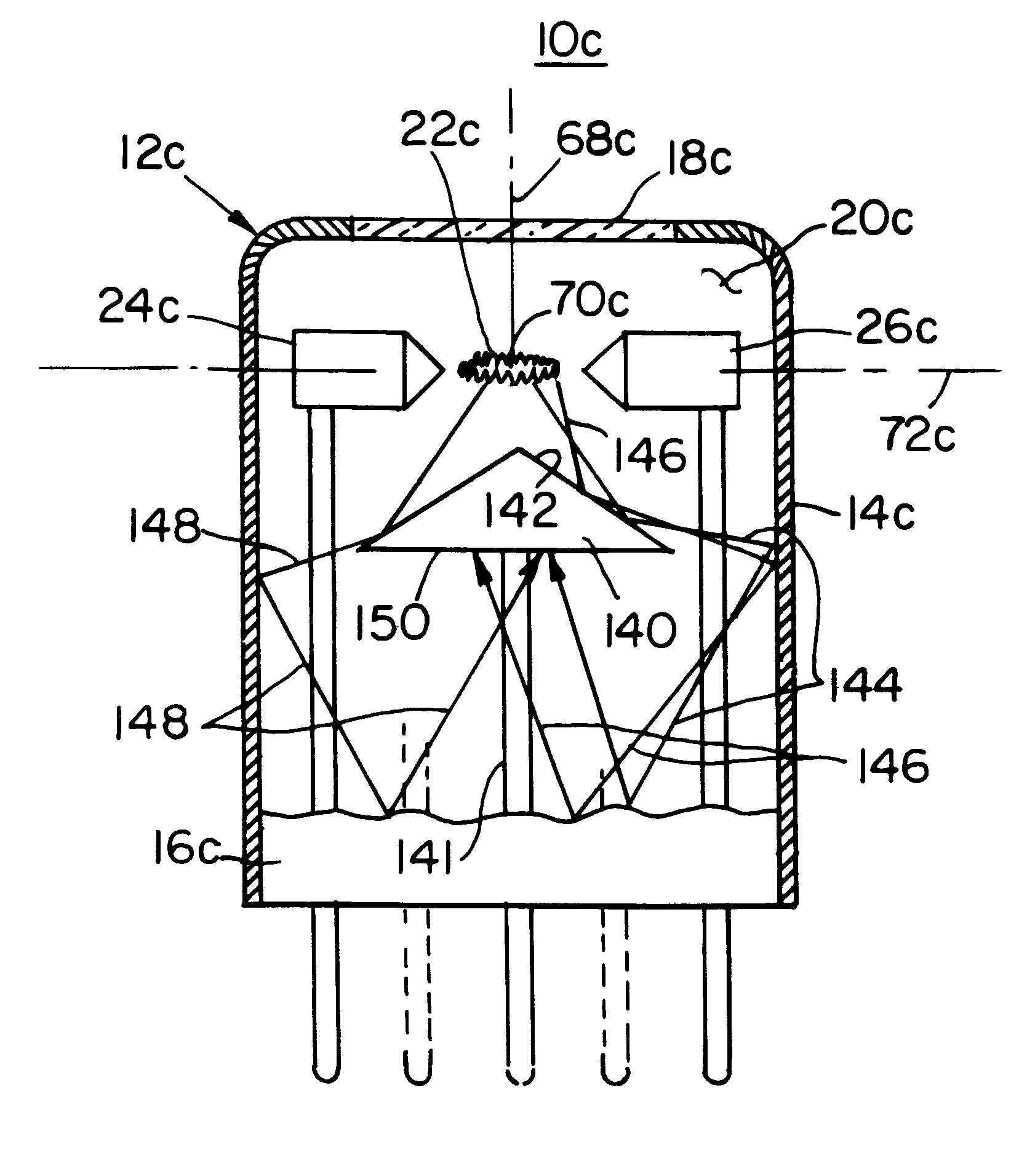
FIG. 4 is a ray diagram similar to FIG. 3 of an arc lamp with the internal spherical reflector of this invention showing the redirecting of rearwardly directed radiation and elimination of optical noise; and

FIG. 5 is a view of the arc lamp of FIG. 1 with a deflector only and no spherical mirror.

There is shown in FIG. 1 an arc la...


PUM


Abstract

An arc lamp includes a housing; an inert gas in the housing; a pair of spaced electrodes in the housing for establishing an arc in the gas to generate a radiation output; a window in the housing for transmitting forward radiation generated by the arc; and a spherical reflector on the opposite side of the electrodes from the window and having its center disposed in the arc for redirecting rearward radiation through the center to add to the forward radiation transmitted through the window.

Description

This invention relates to an arc lamp, and more particularly to such an arc lamp pulsed or continuous having an internal spherical reflector and / or a back scatter deflector.BACKGROUND OF INVENTIONConventional arc lamps, pulsed or continuous, provide a high energy density, high intensity, sharply defined source which is desirable in a number of applications. The high energy density and high intensity make arc lamp sources desirable in spectroscopy where the chemical sensitivity is a direct function of the energy density at the target sample. The high energy density and high intensity are also useful in miniaturization applications such as in fiber optic light transmission for endoscopic uses and generally in photographic illumination applications where a high intensity minute controlled source of illumination is essential. One shortcoming of such lamps is that more than half of the radiation generated is lost because of backscattering of the rearward directed radiation within the arc...

Claims


Application Information

Patent Timeline
Patent Type & Authority Patents(United States)
IPC IPC(8): H01J61/30H01J61/35
CPCH01J61/30H01J61/35H01J61/40
Inventor CAPOBIANCO, ROBERT A.
Owner EXCELITAS TECH
Why Eureka
Try Eureka