Wavelength Division Multiplexing Passive Optical Network System

a passive optical network and wavelength division technology, applied in wavelength division multiplex systems, electromagnetic transceivers, multi-component communication, etc., can solve the problems of ineffective cost-effective addition of fibers and additional fibers to address bandwidth issues, limited bandwidth over such networks, and limited services to customers, so as to reduce optical noise, reduce the use of fibers and components, and increase the upstream and downstream data bandwidth.

Inactive Publication Date: 2014-12-04
TELEKOM MALAYSIA BERHAD
View PDF10 Cites 9 Cited by
  • Summary
  • Abstract
  • Description
  • Claims
  • Application Information

AI Technical Summary

Benefits of technology

[0008]Another aspect of this disclosure is to provide a WDM PON system which is capable of increasing the upstream and downstream data bandwidth stream with minimal usage of fibers and components.
[0009]Still another aspect of this disclosure is to provide a WDM PON system that enables the change of transmission paths of the signals carrying the data.
[0010]Yet another aspect of this disclosure is to provide a WDM PON system that reduces optical noise with the addition of isolators to prevent the happening of signal reflection in the system.

Problems solved by technology

Transmission over such networks may be limited by the increasing data demand on existing PON.
Limited bandwidth often results in limited services being provided to customers.
Added expense and investment from deploying additional fibers to address these bandwidth issues is not cost effective.

Method used


Image

  • Wavelength Division Multiplexing Passive Optical Network System
  • Wavelength Division Multiplexing Passive Optical Network System
  • Wavelength Division Multiplexing Passive Optical Network System

Examples


Embodiment Construction

[0015]While the preferred embodiments of the invention have been illustrated and described, it will be clear that the invention is not limited to theses embodiments only. Numerous modifications, changes, variations, substitutions and equivalents will be apparent to those skilled in the art without parting from the spirit and scope of the invention.

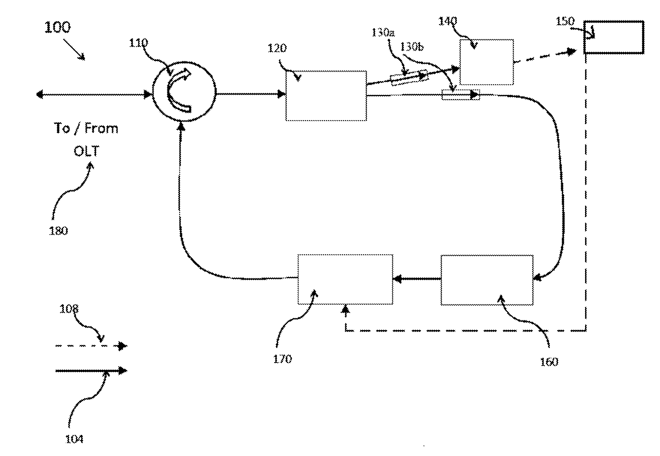
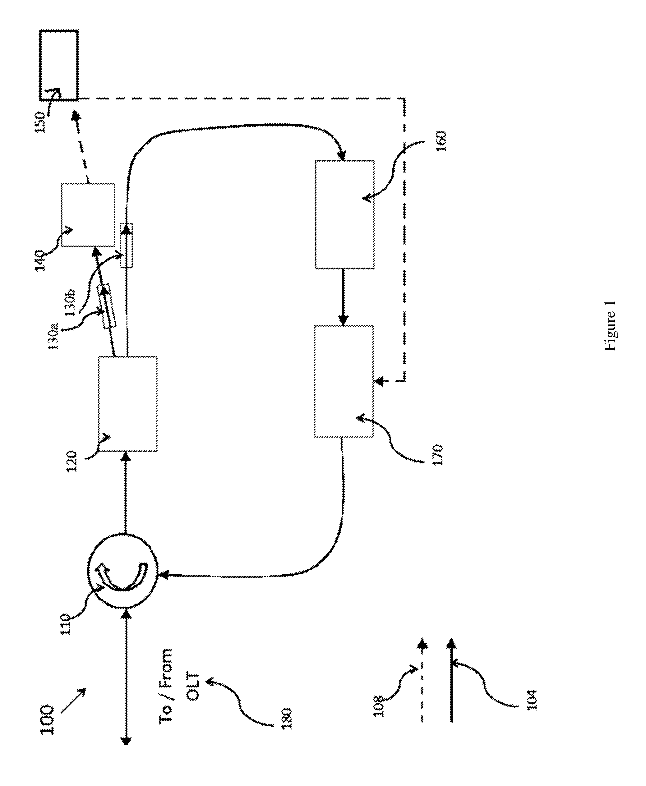
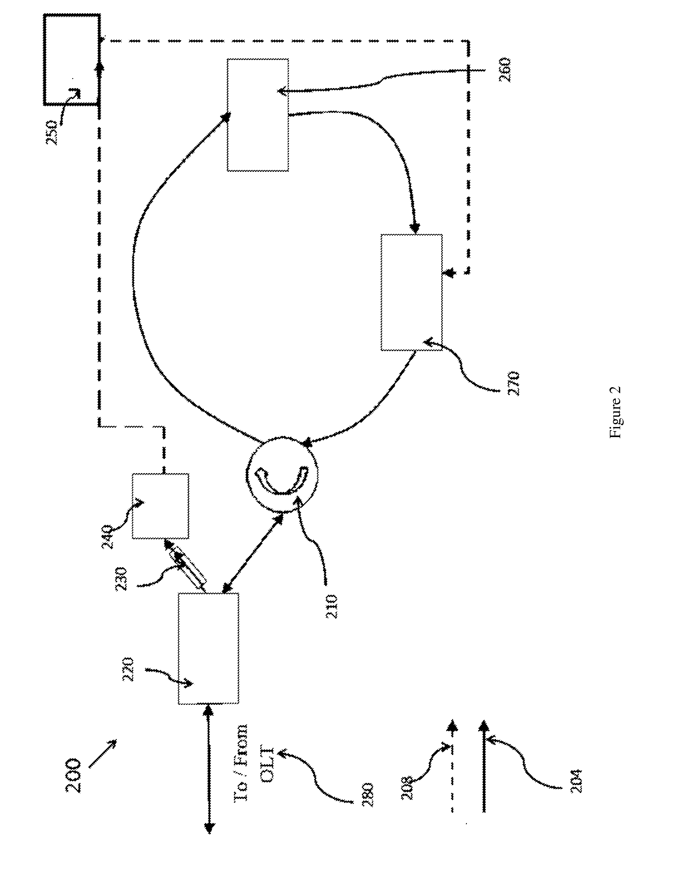
[0016]It is to be understood that the present embodiments are described in terms of a passive optical network (PON); however, other optical networks can be contemplated for the present teachings. While FIG. 1 and FIG. 2 show illustrative optical hardware configurations, these configurations may be reconfigured or combined to provide functionality within the scope of the present principles.

[0017]The present invention in the form of one or more exemplary embodiments will now be described. Persons of ordinary skill in the art will realize that the following description of the present invention is illustrative only and not in any way limiting....


PUM


Abstract

This disclosure describes a wavelength division multiplexing passive optical network system (100) comprising an optical line terminal (180) for controlling transmission of data that are carried by optical signals across the optical network system along an upstream or downstream path; a signal modulating loop circuit including a circulator (110) connected to the optical line terminal (180) for determining the transmission paths of the optical signals; a splitter (120) connected to the circulator (110) for splitting the optical signals into a first portion of optical signals and a second portion of optical signals according to a predetermined ratio; an amplifier (160) connected to the splitter (120) for amplifying the second portion of optical signals; and a modulator (170) connected in between the amplifier (160) and the splitter (120) for modulating the amplified second portion of optical signals to be transmitted to the circulator (110); a converter (140) connected to the splitter (130) for converting the first portion of optical signals into electrical signals; and one or more optical network units (150) connected in between the converter (140) and modulator (170) for receiving the electrical signals from the converter (140), and transmitting electrical signals to the modulator (170) for converting the electrical signals into optical signals to be transmitted together with the amplified second portion of optical signals to the optical line terminal (180); wherein the circulator (110) directs the optical signals received from the modulator (170) to the splitter (120) for being transmitted back into the signal modulating loop circuit and/or towards the optical network units along the downstream path, or towards the optical line terminal along the upstream path.

Description

[0001]The present application claims priority under 35 U.S.C. §119 to Malaysian Application No. P1 2013002000, filed May 31, 2013, and hereby incorporated by reference in its entirety.FIELD OF INVENTION[0002]The invention disclosed here relates in general to a wavelength division multiplexing passive optical network (WDM-PON) system with an architecture that enables change of transmission paths for signals carrying data and increase of data bandwidth with minimal application of fibers and components.BACKGROUND OF THE INVENTION[0003]A passive optical network (PON) is a point-to-multipoint network architecture in which unpowered optical splitters are used to enable a single optical fiber to serve multiple premises. A PON typically includes an Optical Line Terminal (OLT) at the central office of the service provider that is connected to a number of Optical Network Units (ONUs) near the end users.[0004]In operation, downstream signals are broadcast from the OLT to the ONUs on a shared f...

Claims


Application Information

Patent Timeline
Patent Type & Authority Applications(United States)
IPC IPC(8): H04B10/2575H04J14/02H04B10/516
CPCH04B10/2575H04J14/02H04B10/516H04B10/2587H04J2014/0253H04B10/40H04B10/2589
Inventor SALLEH, MOHD. SHAHRIL BINISMAIL, UMMI SUPYA BINTIAHMAD, ASMAHANIM BTESSI, DREES ANDRIYANTO M.ZAMZURI BIN, MUHAMMADMANAF, ZULHEDRY ABDUL
Owner TELEKOM MALAYSIA BERHAD
Why Eureka
Try Eureka