End point detection in workpiece processing

a technology for workpieces and end points, applied in the field of workpiece processing, can solve the problems of affecting the accuracy of end point detection, and wasting time and process chemicals, and achieve the effect of improving accuracy and reducing optical nois

Active Publication Date: 2007-05-31
APPLIED MATERIALS INC
View PDF8 Cites 8 Cited by
  • Summary
  • Abstract
  • Description
  • Claims
  • Application Information

AI Technical Summary

Benefits of technology

[0005] A novel end point detection system has now been developed which overcomes the drawbacks of existing systems and also provides additional advantages. In one aspect, the present end point detection system diffuses emitted light directed at the workpiece, and / or reflected light impinging on a light detecting element. By diffusing the light, optical noise (for example resulting from a spray of liquid inside the process chamber) is greatly reduced. Accurate end point detection is improved.
[0006] In another and separate aspect, a light emitter and a light detector are located within a workpiece process chamber. A housing around the light emitter and the light detector in the process chamber, is at least partially translucent, allowing sufficient light to pass through to perform end point detection. The housing may also prevent potentially corrosive process liquids or gasses from coming into contact with the light emitter and detector. Placing the light emitter and detector within the process chamber provides for accurate end point detection with a highly compact system. Precise positioning or alignment of optical elements is also not necessary, as the system does not rely on specular reflected light.

Problems solved by technology

Extensive processing after the end point can waste time and process chemicals, and even damage the workpiece in more extreme cases.
On workpieces patterned with photoresist, continuing to process the workpiece beyond the end point may undercut the photoresist and decrease the critical dimension of the microscopic device features formed on the workpiece.
On the other hand, if a process is stopped before the correct end point, the workpiece will not be fully processed.
As a result, the workpiece would then require re-work, or have to be discarded.
However, in cases where the intensity change is slight, for example where color change between films is subtle, or where the percentage of area cleared is low, electronic or optical noise can mask detection of the endpoint.
As a result, stray light may penetrate into the chamber, making it more difficult to achieve accurate optical measurements.
Reflection and diffraction of light in the process chamber by droplets of chemical process liquids may also create errors in optical measurements.
As a result engineering challenges remain in the design of optical end point detection.

Method used


Image

  • End point detection in workpiece processing
  • End point detection in workpiece processing
  • End point detection in workpiece processing

Examples


Embodiment Construction

[0021] The systems and methods described may be used to process workpieces, such as semiconductor wafers, flat panel displays, hard disk media, CD glass, memory and optical media, MEMS devices, and various other substrates on which micro-electronic, micro-mechanical, or micro-electromechanical devices are or can be formed. These are collectively referred to here as workpieces or wafers. Descriptions here of semiconductors, or the semiconductor industry or manufacturing processes, also includes the workpieces listed above, and their equivalents.

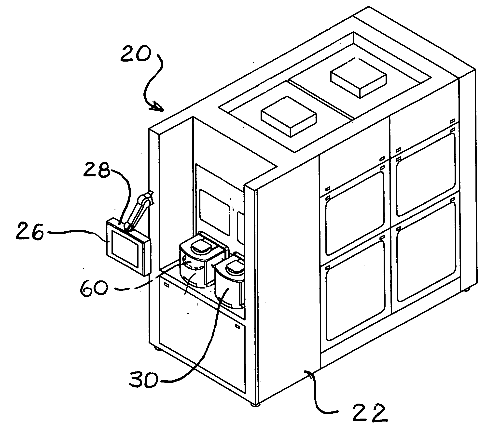
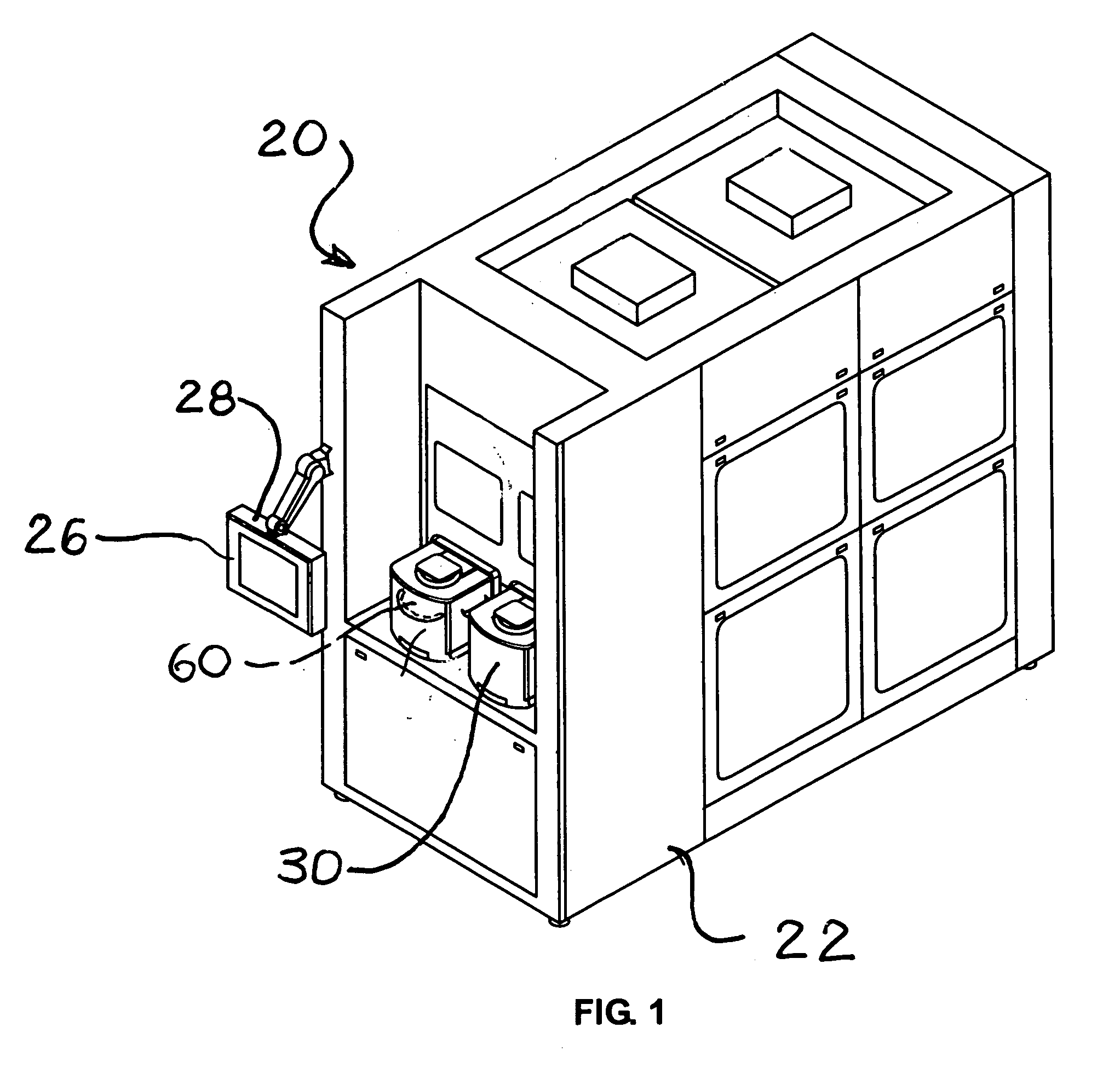
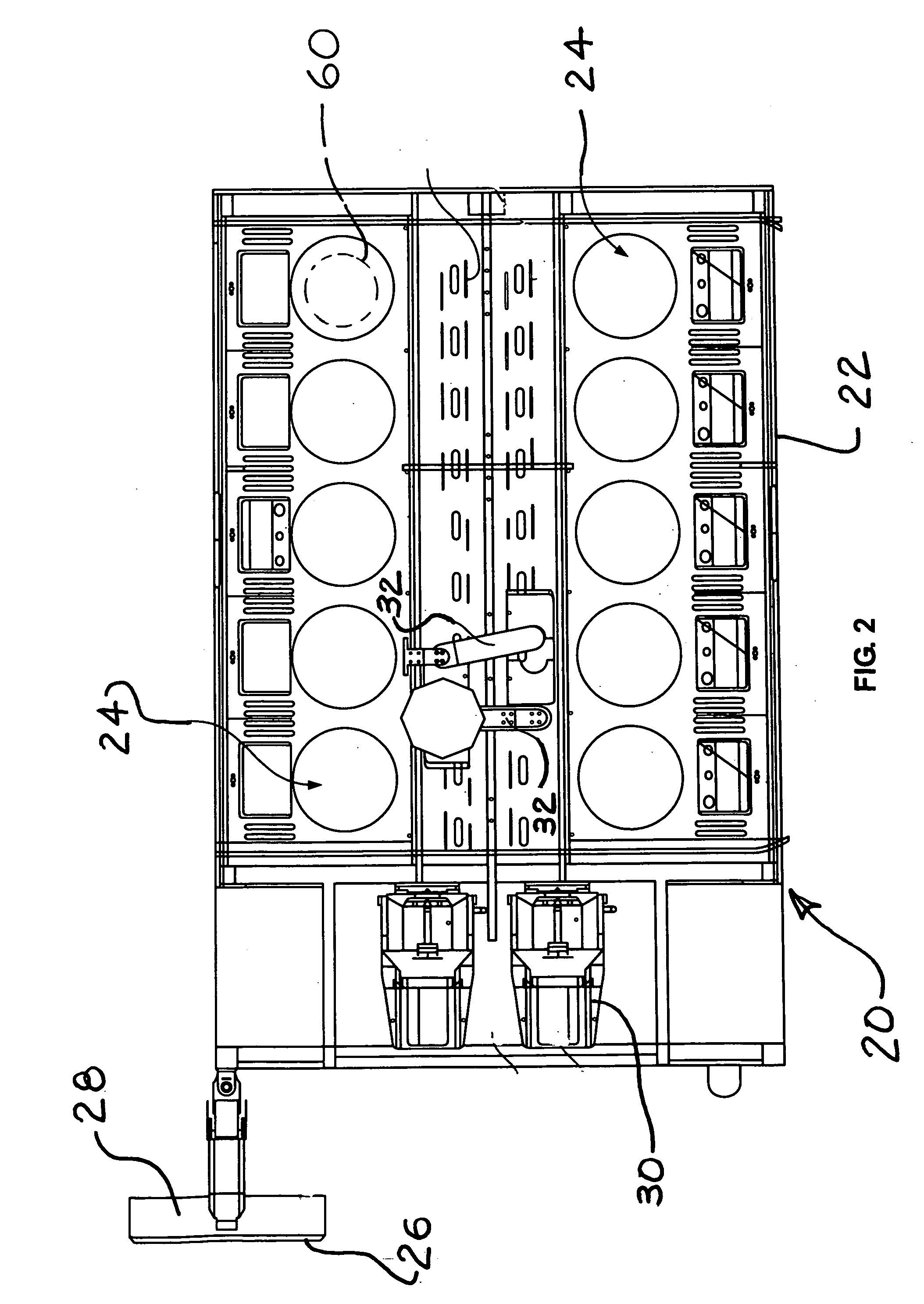
[0022] Turning now to the drawings, as shown in FIGS. 1 and 2, as one example, a processing system 20 includes one or more processors 24 within an enclosure 22. A control / display panel 26 is typically provided with the processing system 20, to allow system operators to monitor various operations, as well as entering or modifying system instructions and software. One or more computer controllers 28 is also typically provided with the processin...


PUM


Abstract

In a workpiece process end point detection system, light is diffused and then light intensity or color is sensed. Optical noise is greatly reduced and more accurate end point detection can be made. A light emitter and a light sensor may be located within a workpiece process chamber. A housing around the light emitter and the light sensor seals out process fluids and also diffuses light passing through. The diffused light may be optically filtered before reaching the light sensor.

Description

BACKGROUND OF THE INVENTION [0001] The invention relates to processing of workpieces, such as semiconductor wafers. Semiconductor and similar microscale devices are typically manufactured by performing many separate steps on substrates or wafers. The workpieces are often coated or plated with multiple layers or films of different materials. Process chemicals, typically etchants in liquid form, are applied to the workpieces to selectively remove one or more layers. Often, a layer on the workpiece is patterned generally using photolithographic methods, and only portions of the layer are removed. [0002] In workpiece processing, it is often important to determine the end point of a process. In a layer or film removal process, the end point is defined as the point at which all of the targeted layer has been removed, exposing an underlying layer beneath the targeted layer. Extensive processing after the end point can waste time and process chemicals, and even damage the workpiece in more ...

Claims


Application Information

Patent Timeline
Patent Type & Authority Applications(United States)
IPC IPC(8): G01B11/28
CPCH01L21/67253H01L22/26H01L2924/0002H01L2924/00
Inventor WOODRUFF, DANIEL J.BERNT, MARVIN LOUIS
Owner APPLIED MATERIALS INC
Why Eureka
Try Eureka