Methods and apparatuses for deploying minimally-invasive heart valves

a heart valve and minimally invasive technology, applied in the field of medical devices, can solve the problems of long recovery period and particularly invasive open heart surgery

Inactive Publication Date: 2009-07-07
EDWARDS LIFESCIENCES CORP
View PDF71 Cites 409 Cited by
  • Summary
  • Abstract
  • Description
  • Claims
  • Application Information

AI Technical Summary

Benefits of technology

[0011]In a still further embodiment, each deployment member may comprise a pad that is coupled to a respective proximal and distal end cap disposed along the catheter shaft, the pads being radially displaceable with respect to the associated end cap, wherein the proximal and distal end caps are axially movable with respect to each other. There may be two of the actuating shafts, each shaft controlling a plurality of flexible tongs having column strength that extend between one of the end caps and attach to the associated pads, wherein axial movement of each shaft shortens or lengthens the radial extent of the flexible tongs controlled thereby so as to radially displace the attached pads.

Problems solved by technology

Such open heart surgery is particularly invasive and involves a lengthy and difficult recovery period.

Method used


Image

  • Methods and apparatuses for deploying minimally-invasive heart valves
  • Methods and apparatuses for deploying minimally-invasive heart valves
  • Methods and apparatuses for deploying minimally-invasive heart valves

Examples


Embodiment Construction

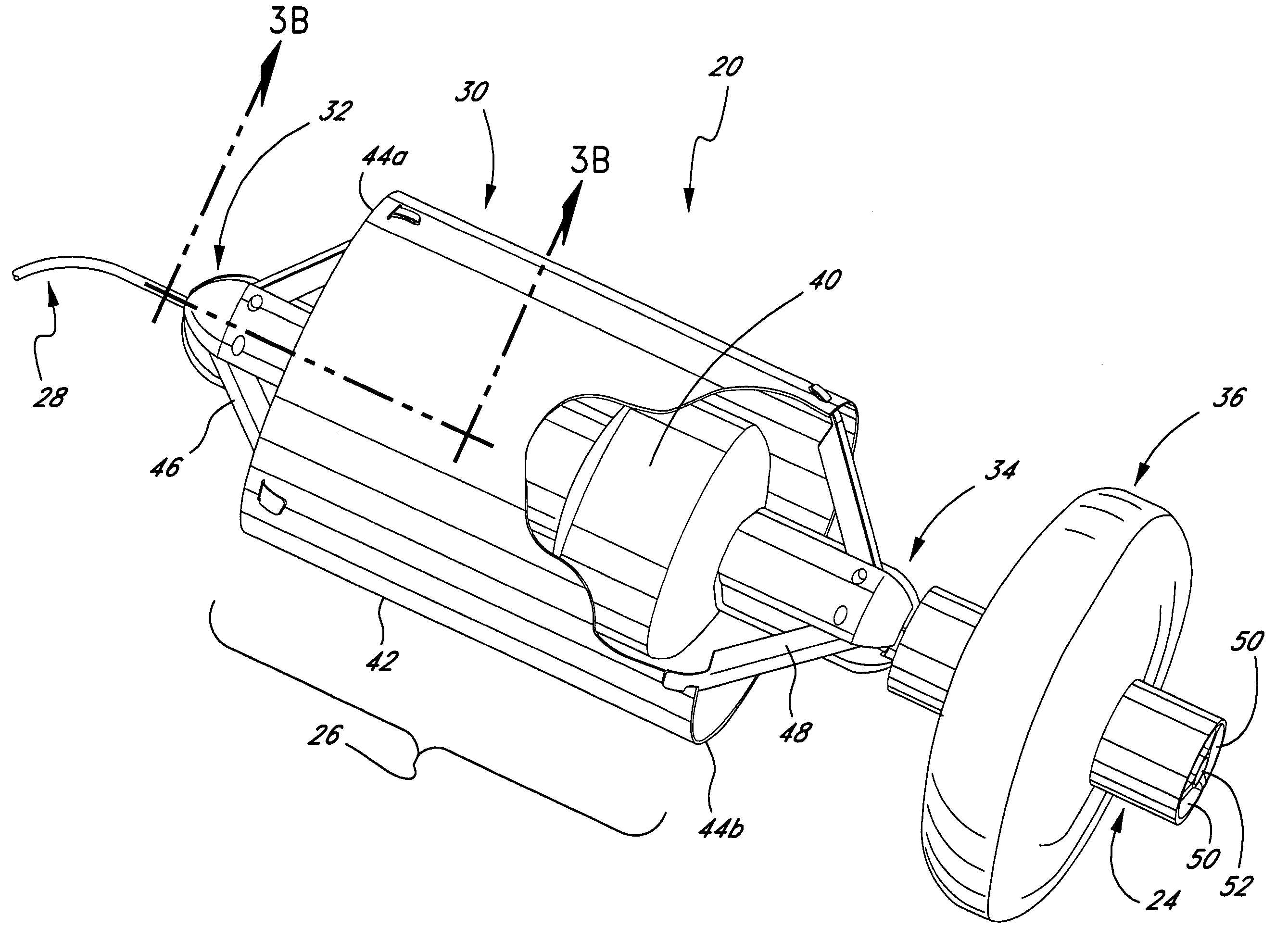
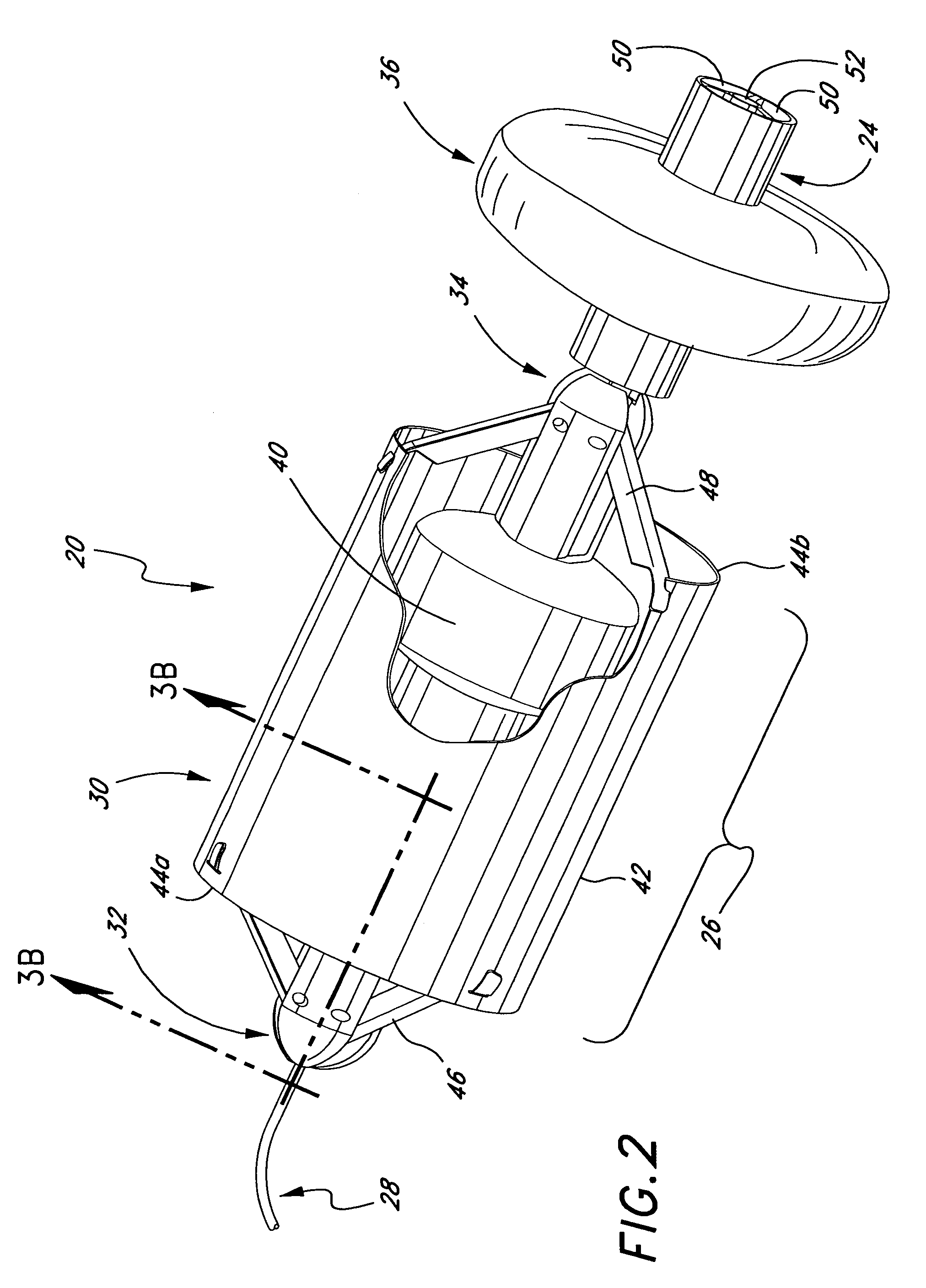
[0044]The present invention discloses a number of expandable heart valves for implantation in a host annulus, or host tissue adjacent the annulus. The valves may be implanted in any of the four valve positions within the heart, but are more likely to be used in replacing the aortic or mitral valves because of the more frequent need for such surgery in these positions. The patient may be placed on cardiopulmonary bypass or not, depending on the needs of the patient.

[0045]A number of expandable prosthetic heart valves are disclosed in co-pending U.S. application Ser. No. 09 / 815,521 that are initially rolled into a tight spiral to be passed through a catheter or other tube and then unfurled or unrolled at the implantation site, typically a valve annulus. These will be denoted “rolled heart valves” and comprise one- or two-piece sheet-like stent bodies with a plurality of leaflet-forming membranes incorporated therein. Various materials are suitable for the stent body, although certain ...


PUM


Abstract

A system for delivering and deploying a self-expandable heart valve includes a deployment mechanism that engages the valve and regulates the rate of expansion of both the proximal and distal ends thereof. The deployment mechanism may include a plurality of distal fingers and a plurality of proximal fingers that engage the end portions of the heart valve. Controlled radial movement of the fingers regulates the expansion of the heart valve such that the proximal and distal ends radially expand at the same rate. A stabilization balloon may be used to axially and radially locate the deployment mechanism relative to the site of implantation. Methods of operation of the delivery and deployment mechanism include regulating the rate of self-expansion of the valve and forcing the valve outward into its fully expanded configuration utilizing the same or different means.

Description

FIELD OF THE INVENTION[0001]The present invention relates generally to medical devices and particularly to methods and devices for deploying expandable heart valve prostheses especially for use in minimally-invasive surgeries.BACKGROUND OF THE INVENTION[0002]Prosthetic heart valves are used to replace damaged or diseased heart valves. In vertebrate animals, the heart is a hollow muscular organ having four pumping chambers: the left and right atria and the left and right ventricles, each provided with its own one-way valve. The natural heart valves are identified as the aortic, mitral (or bicuspid), tricuspid and pulmonary valves. Prosthetic heart valves can be used to replace any of these naturally occurring valves.[0003]Where replacement of a heart valve is indicated, the dysfunctional valve is typically cut out and replaced with either a mechanical valve or a tissue valve. Tissue valves are often preferred over mechanical valves because they typically do not require long-term trea...

Claims


Application Information

Patent Timeline
Patent Type & Authority Patents(United States)
IPC IPC(8): A61F2/24
CPCA61F2/2412A61F2/243A61F2/2409A61F2/2427
Inventor YANG, JIBINHENEVELD, SR., SCOTT HYLERPEASE, MATTHEW LANEWALSH, BRANDON G.
Owner EDWARDS LIFESCIENCES CORP
Why Eureka
Try Eureka