Over current protection circuit and method

a protection circuit and over current technology, applied in the direction of dc-dc conversion, power conversion systems, electrical equipment, etc., can solve the problems of the inability to provide ocp in the response to an overcurrent situation, and the inability to quickly reduce the energy flow. , to achieve the effect of efficient and reliabl

Inactive Publication Date: 2009-07-07
INFINEON TECH AG
View PDF1 Cites 63 Cited by
  • Summary
  • Abstract
  • Description
  • Claims
  • Application Information

AI Technical Summary

Benefits of technology

[0011]These and other problems are generally solved or circumvented, and technical advantages are generally achieved, by preferred embodiments of the present invention which provide an efficient and reliable circuit and methods to implement OCP in a...

Problems solved by technology

However, in another popular circuit topology for switched-mode power converters, this rapid response to an over-current situation to provide OCP is not possible.
However in converters using this topology, when an over-current condition is detected, it is not possible to rapidly reduce the energy flow, because the VCO requires at least one and perhaps several cycles to respond to a change in the output frequency desired.
A first disadvantage of these approaches is that they require ad...

Method used


Image

  • Over current protection circuit and method
  • Over current protection circuit and method
  • Over current protection circuit and method

Examples


Embodiment Construction

[0025]The making and using of the presently preferred embodiments are discussed in detail below. It should be appreciated, however, that the present invention provides many applicable inventive concepts that can be embodied in a wide variety of specific contexts. The specific embodiments discussed are merely illustrative of specific ways to make and use the invention, and do not limit the scope of the invention or the appended claims.

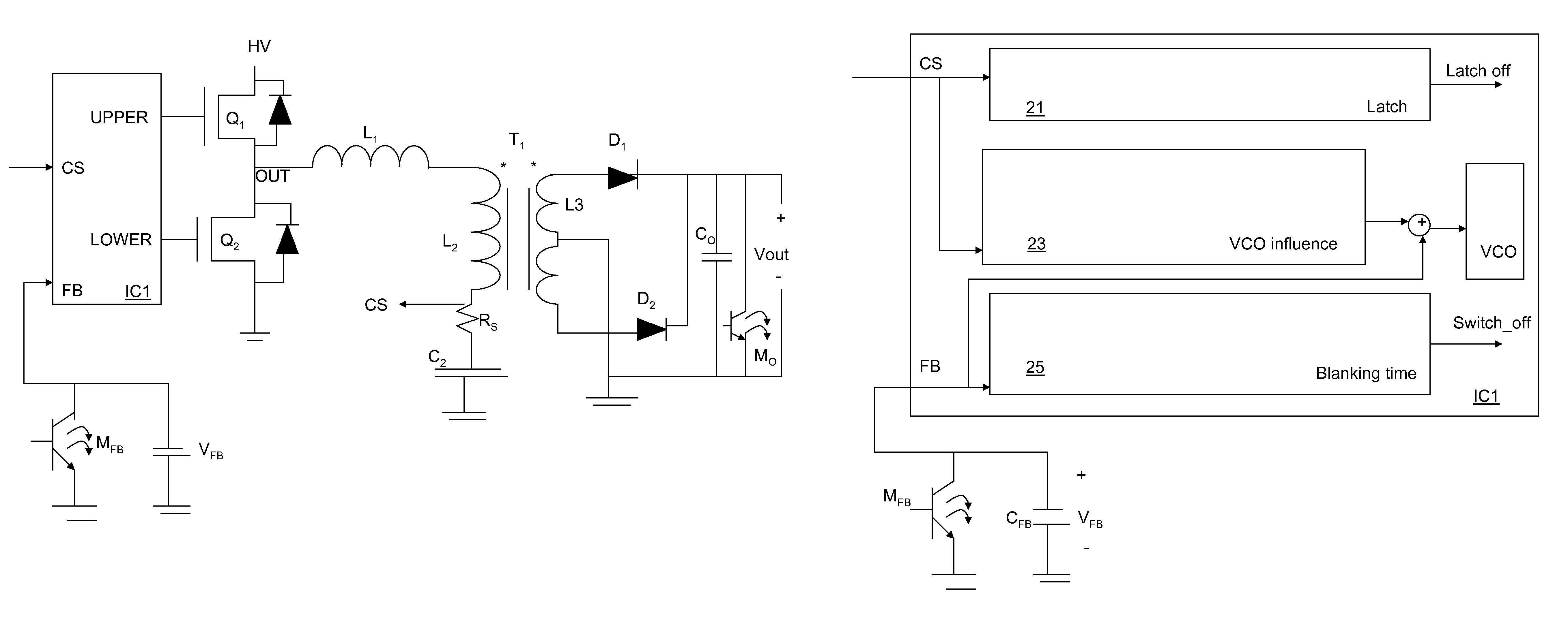
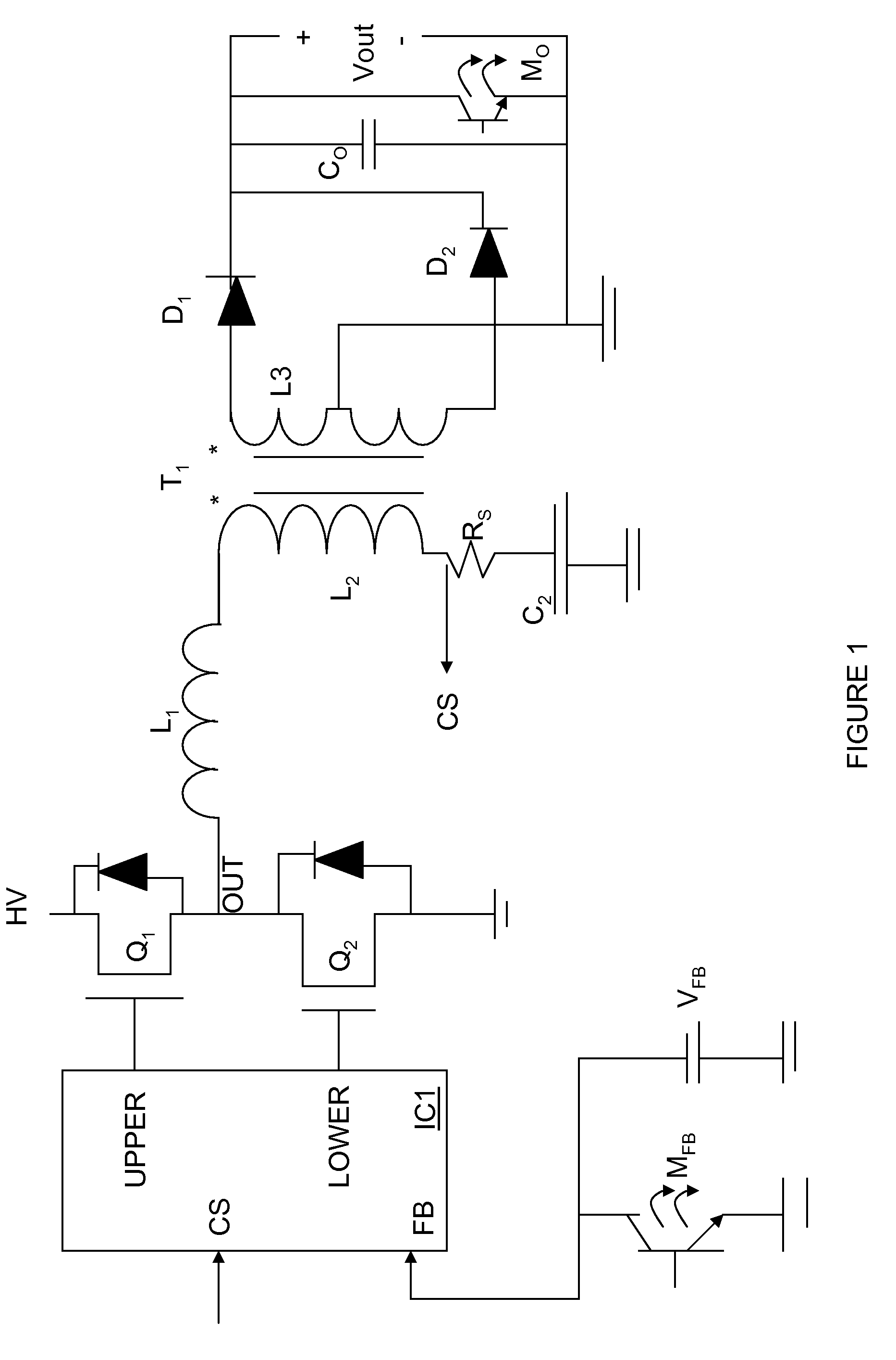
[0026]The present invention will be described with respect to preferred embodiments in a specific context, namely a switched mode power supply (SMPS) using an LLC half-bridge topology. The embodiments of the invention may also be applied, however, to other circuits where a converter circuit is used with a coil or inductor.

[0027]With reference now to FIG. 1, there is shown an exemplary half-bridge converter circuit in an application using an exemplary controller IC labeled IC1. A high voltage supply HV is coupled to an upper driver transistor Q1 that has...


PUM


Abstract

Circuit and method for providing over-current and overloading protection with a single additional pin. A converter controller circuit is provided that includes a voltage controlled oscillator and outputs upper and lower gating signals for driving the upper and lower driving transistors in a voltage converter, for example, in an inductor-inductor capacitor half-bridge circuit topology. A current sense input pin of the circuit receives a voltage corresponding to the current flowing in the half-bridge circuit. A feedback input pin has an external capacitor coupled to it and receives a voltage from an output voltage sensor at the output terminals. Over-current protection is provided by sensing the voltage at the current sense input pin with no external components needed. Overload protection is provided by utilizing the external feedback capacitor and the feedback input pin during overload conditions. Methods for providing over-current and overload protection are disclosed.

Description

TECHNICAL FIELD[0001]The present invention relates generally to a system and method to improve the operation of a switched-mode power supply converter and, more particularly, to a system and method for efficient operation of an over-current protection (OCP) function and an over-load protection function (OLP) in a DC-to-DC converter circuit.BACKGROUND[0002]Generally, switching converters provides a DC output voltage from an input voltage. Circuit topologies provide a variety of approaches, including pulse width modulation (PWM) and pulse frequency modulation (PFM) topology converters. The choice of topology is determined by the needs of a particular application.[0003]OCP is typically provided in these circuits and systems to protect the components from permanent damage in the event too much current is flowing in the circuitry. The known circuit topology presently being used must be considered in order to explain the OCP approaches. In converter applications where a PWM scheme is used...

Claims


Application Information

Patent Timeline
IPC IPC(8): H02H3/08H02H9/02H02H3/00H02H3/20H02H9/04H02H3/22H02H7/00H02H9/00
CPCH02M3/3376H02M1/32
Inventor GONG, XIAOWUHE, YICHAN, TUCK MENG
Owner INFINEON TECH AG
Why Eureka
Try Eureka