High-energy capacitors for implantable defibrillators
What is Al technical title?
Al technical title is built by PatSnap Al team. It summarizes the technical point description of the patent document.
a high-energy, defibrillator technology, applied in the field of electrolytic capacitors, can solve the problems of failure to rhythmically expand and contract, complete loss of cardiac function and death within minutes, and capacitors that don't work as well as expected
Inactive Publication Date: 2009-07-07
CARDIAC PACEMAKERS INC
View PDF111 Cites 8 Cited by
Summary
Abstract
Description
Claims
Application Information
AI Technical Summary
This helps you quickly interpret patents by identifying the three key elements:
Problems solved by technology
Method used
Benefits of technology
Problems solved by technology
Many of these cardiac arrests stem from the heart chaotically twitching, or fibrillating, and thus failing to rhythmically expand and contract as necessary to pump blood.
Fibrillation can cause complete loss of cardiac function and death within minutes.
Thus, foils with this type of etching are called “core etched.” Although core-etched foils have more surface area, they don't work as well as expected in capacitors with two stacked anode foils, because the solid core layer of one anode foil shields the other anode foil from electrolyte flow.
However, tunnel-etched foils not only have less surface area than core-etched foils but are also quite brittle and tend to break easily, particularly when rolling or winding the foils to form cylindrical capacitors.
Method used
Image
Click on the blue label to locate the original text in one second.
Reading with bidirectional positioning of images and text.
Examples
Embodiment Construction
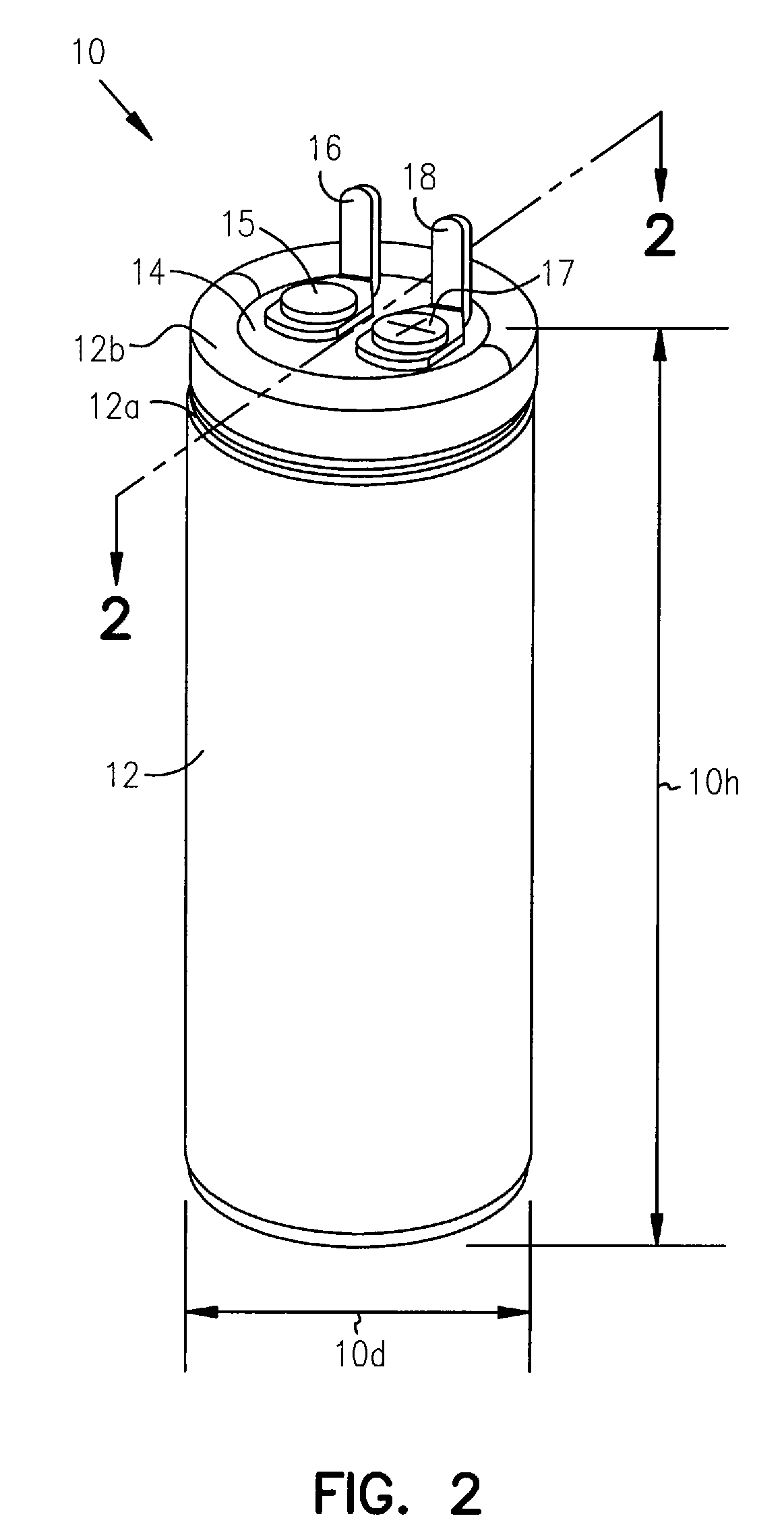
[0021]The following detailed description, which references and incorporates FIGS. 1-7, describes and illustrates one or more exemplary embodiments of the invention, specifically a new foil structure and method of manufacture, several new foil assemblies, new capacitors incorporating the foil structure and foil assemblies, and an implantable defibrillator incorporating one or more of the new capacitors. These embodiments, offered not to limit but only to exemplify and teach, are shown and described in sufficient detail to enable those skilled in the art to implement or practice the invention. Thus, where appropriate to avoid obscuring the invention, the description may omit certain information known to those of skill in the art.
Exemplary Foil Structure and Methods of Manufacture
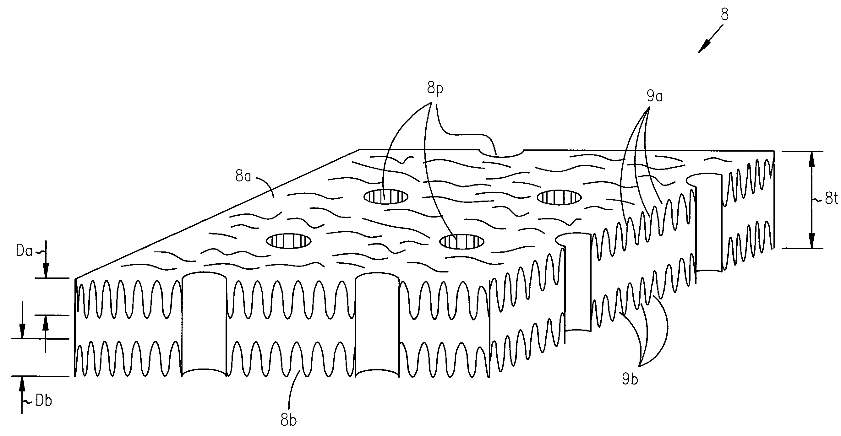
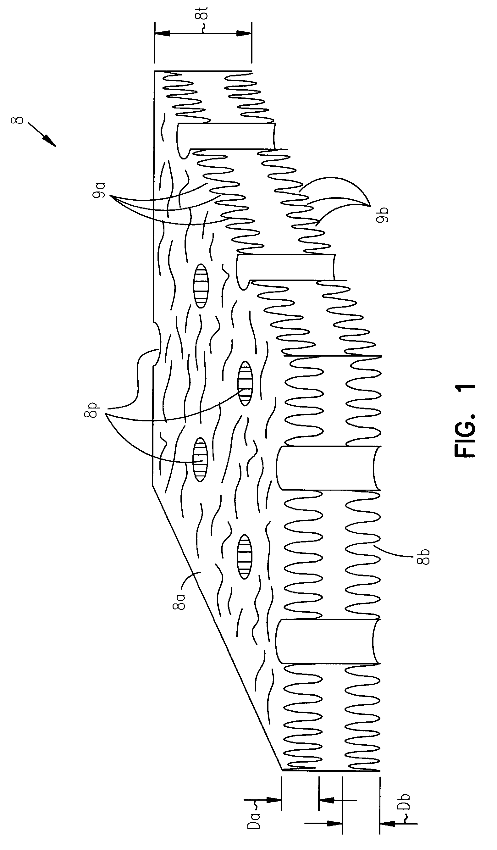
[0022]FIG. 1 shows an enlarged perspective view of a foil structure 8 which the inventors call a “perforated-core-etched” foil. Foil structure 8 can be made of aluminum, tantalum, hafnium, niobium, titanium, z...
PUM
Abstract
Implantable defibrillators are implanted into the chests of patients prone to suffering ventricular fibrillation, a potentially fatal heart condition. A critical component in these devices is an aluminum electrolytic capacitor, which stores and delivers life-saving bursts of electric charge to a fibrillating heart. To reduce capacitor size, manufacturers have developed special aluminum foils, such as core-etched and tunnel-etched aluminum foils. Unfortunately, core-etched foils don't work well in multiple-anode capacitors, and tunnel-etched foils are brittle and tend to break when making some common types of capacitors. Accordingly, the inventors devised a new foil structure having perforations and cavities. In an exemplary embodiment, each perforation and cavity has a cross-sectional area, with the perforations having a larger, for example, 2 to 100 times larger, average cross-sectional area than the cavities. Other embodiments of the invention include foil assemblies, capacitors, and implantable defibrillators that benefit from properties of the new foil structure.
Description
CROSS-REFERENCE TO RELATED APPLICATION(S)[0001]This application is a continuation of U.S. patent application Ser. No. 10 / 424,988, filed on Apr. 28, 2003, now U.S. Pat. No. 7,043,300 which is a continuation of U.S. patent application Ser. No. 09 / 165,779, filed on Oct. 2, 1998, now issued as U.S. Pat. No. 6,556,863, the specifications of which are incorporated herein by reference.[0002]This application is also related to U.S. patent application Ser. No. 09 / 606,633, filed on Jun. 29, 2000, now issued as U.S. Pat. No. 6,421,226 and U.S. patent application Ser. No. 09 / 606,291, filed on Jun. 29, 2000, now issued as U.S. Pat. No. 6,426,864, the specifications of which are incorporated herein by reference.BACKGROUND OF THE INVENTION[0003]The present invention concerns electrolytic capacitors, particularly those for use in medical devices, such as implantable defibrillators.[0004]Every year more than half a million people in the United States suffer from heart attacks, more precisely cardiac...
Claims
Application Information
Patent Timeline
Application Date:The date an application was filed.
Publication Date:The date a patent or application was officially published.
First Publication Date:The earliest publication date of a patent with the same application number.
Issue Date:Publication date of the patent grant document.
PCT Entry Date:The Entry date of PCT National Phase.
Estimated Expiry Date:The statutory expiry date of a patent right according to the Patent Law, and it is the longest term of protection that the patent right can achieve without the termination of the patent right due to other reasons(Term extension factor has been taken into account ).
Invalid Date:Actual expiry date is based on effective date or publication date of legal transaction data of invalid patent.