Depth gauge

a technology of depth gauge and depth gauge, which is applied in the field of depth gauge, can solve the problems of difficult to hook the edge of the hole through the far wall, and achieve the effect of helping the medical care area

Active Publication Date: 2009-07-14
SYNTHES GMBH
View PDF6 Cites 24 Cited by
  • Summary
  • Abstract
  • Description
  • Claims
  • Application Information

AI Technical Summary

Benefits of technology

[0004]Accordingly, it is an object of the present invention to provide a simple and effective tool to measure the depth of a blind hole.
[0005]Another object of the invention herein is to provide an instrument wherein the probe firmly engages to the distal edge of the hole, allowing a precise measurement of the depth of a blind hole.

Problems solved by technology

The disadvantage of these devices is that hooking the edge of the hole through the far wall could be quite difficult, mainly when measuring smaller diameter holes.

Method used


Image

  • Depth gauge
  • Depth gauge
  • Depth gauge

Examples


Embodiment Construction

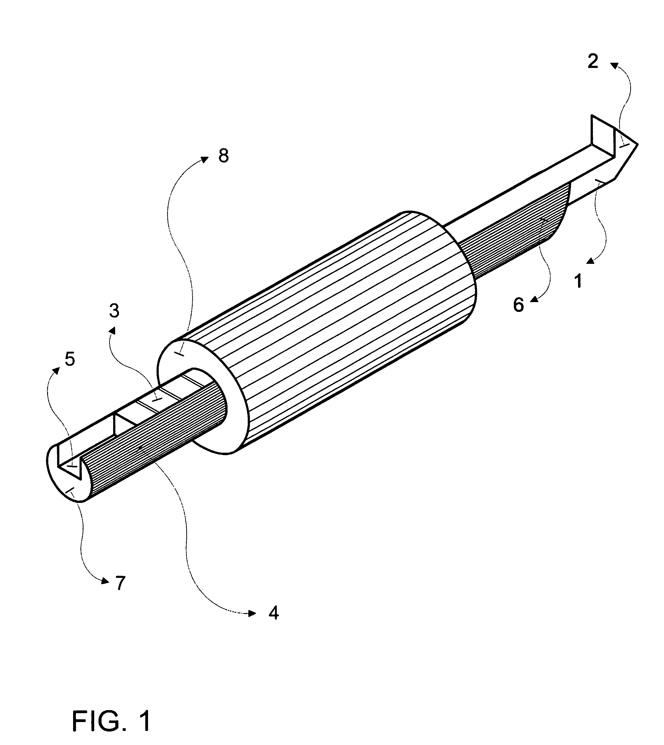
[0016]Hereinafter, a preferred embodiment of the present invention will be described with reference to FIGS. 1-2.

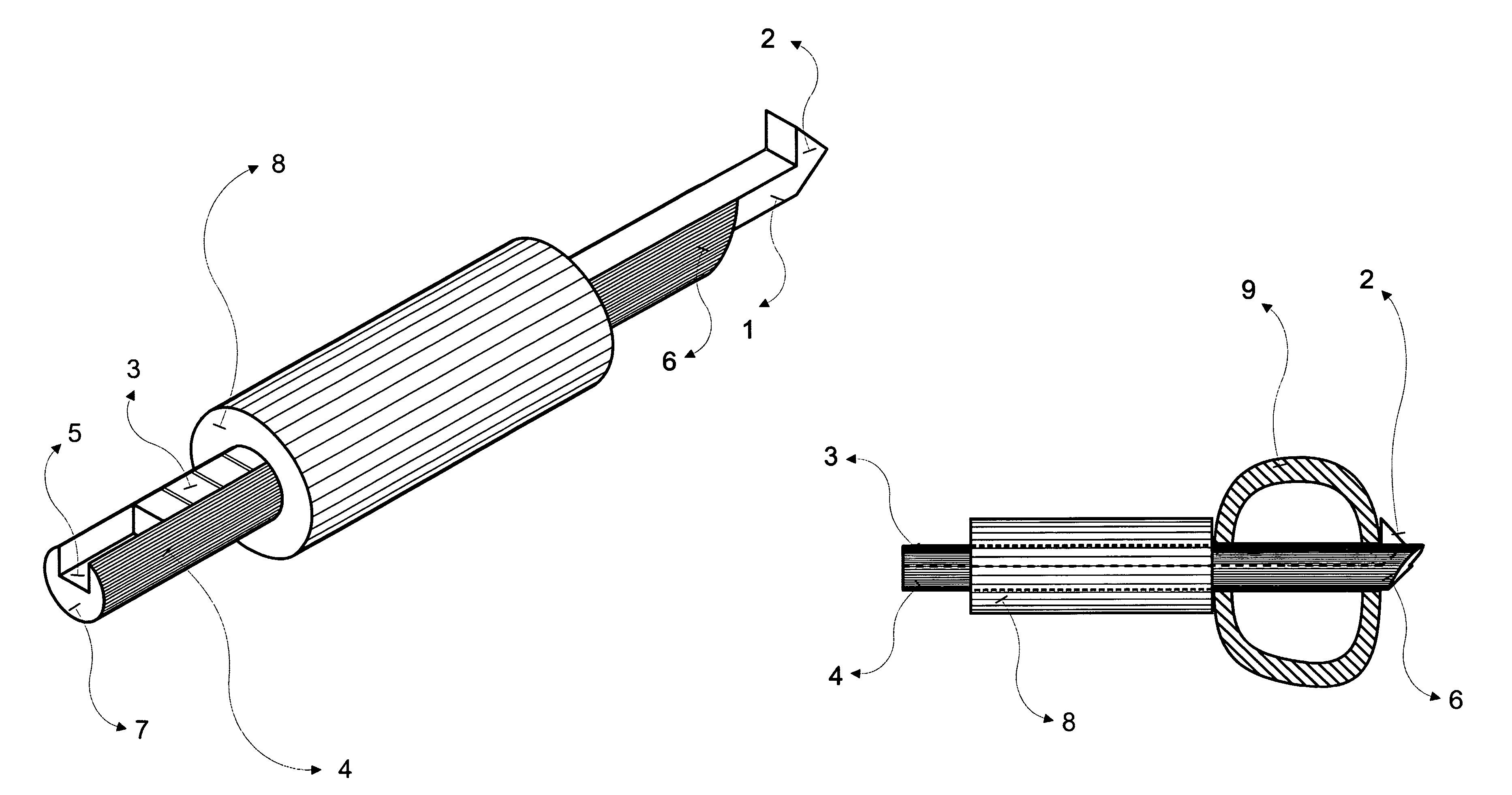
[0017]FIG. 1 shows a preferred embodiment of a depth-measuring tool of the present invention. A probe 1, engaged with groove 5 of a grooved insert 4, is able to slide freely with respect to the grooved insert 4 along the longitudinal axis of the probe 1. The tubular housing 8 is slidably mounted over probe 1 and grooved insert 4.

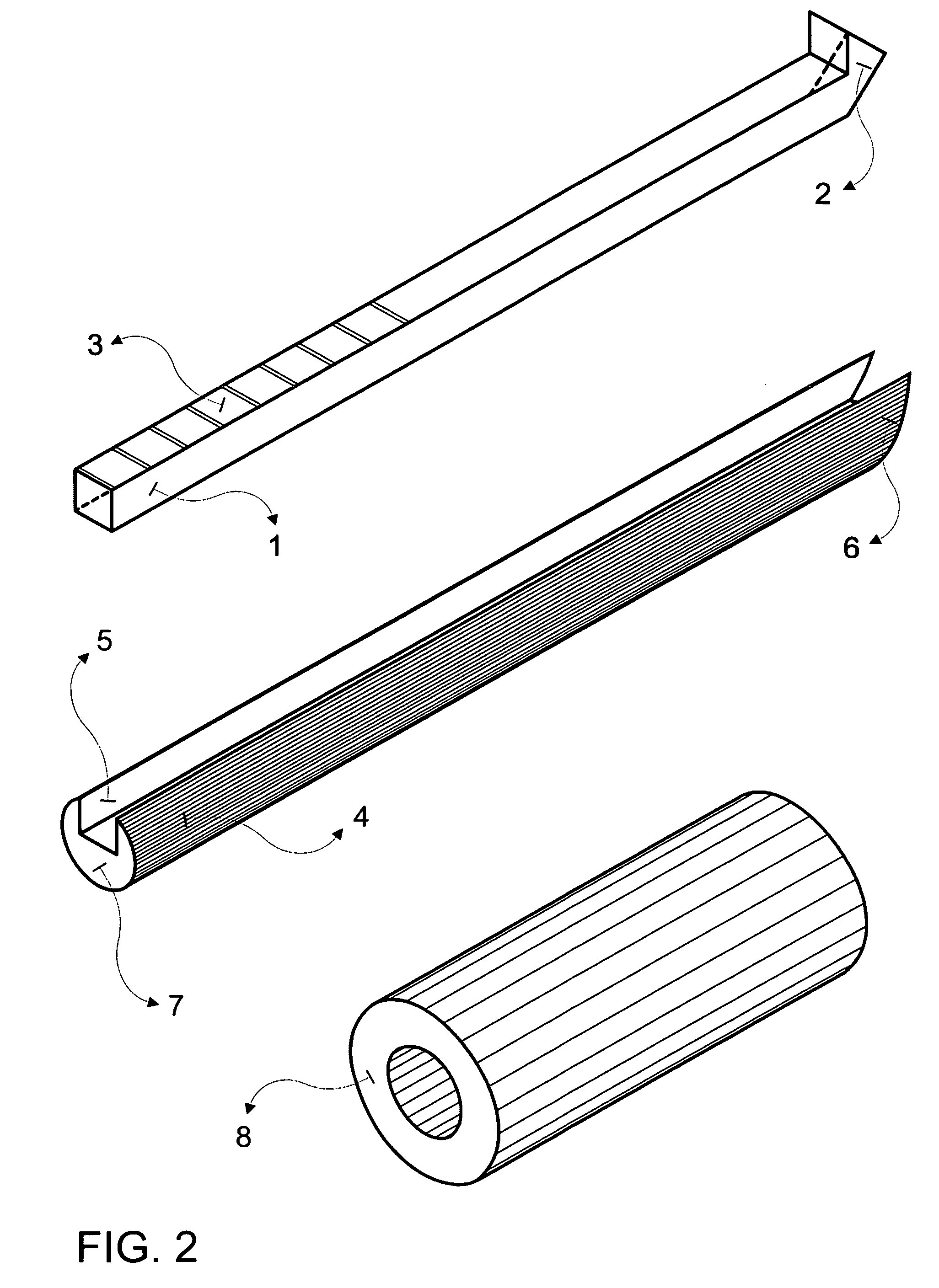
[0018]The disassembled system is clearly seen in FIG. 2, wherein its three components are shown: the probe 1; the grooved insert 4; and the tubular housing 8. The probe has an abutment 2 on its distal end and a scale 3 located at its proximal end. The grooved insert 4 includes a groove 5 to accommodate the probe 1, a proximal end 7, and a tapered distal end 6 designed to avoid impingement against the proximal border of the hole to be measured 10. The tubular housing 8 is sized to accommodate the grooved insert 4 and the probe 1 inside it.

[0019]In ...


PUM


Abstract

A depth gauge for measuring the depth of blind holes in bones and / or nails inserted into bones is provided. The tool includes a probe with an abutment at its end to engage against the distal edge of the blind hole; a tubular body; and a grooved insert. After the probe, slidably disposed within the tubular body, is positioned through the blind hole to be measured, the grooved insert is slid forward inside the tubular body, surrounding the probe, and pushing the probe sideward, towards the blind hole wall. When probe and groove insert are retracted together, they firmly engage against the distal bone wall. The tubular housing is then pushed forward until it abuts against the proximal bone wall, allowing even in small diameter holes, an accurate reading of hole depth on the scale located at the rear end of the probe.

Description

FIELD OF THE INVENTION[0001]The present invention relates to measurement devices, and, more particularly, to depth gauges for determining the depth of holes in bone and / or orthopedic implants inserted into bone.BACKGROUND OF THE INVENTION[0002]It is often necessary to exactly assess the depth of a blind hole. Existing measurement devices have a single hook on one end of a calibrated rod. The rod is inserted through the hole, and after the hook emerges through the opposite, distal wall, the rod is retracted until it abuts against the blind edge of the hole. The disadvantage of these devices is that hooking the edge of the hole through the far wall could be quite difficult, mainly when measuring smaller diameter holes.[0003]For the foregoing deficiencies in the prior art, a new hole depth-measuring instrument that provides a fast and accurate measure is needed. There is a further need to have an instrument wherein the probe firmly engages to the distal edge of the hole, allowing a pre...

Claims


Application Information

Patent Timeline
Patent Type & Authority Patents(United States)
IPC IPC(8): A61B5/107
CPCG01B3/28A61B5/103A61B5/4504A61B5/1072A61B19/46A61B2019/461A61B90/06A61B2090/061G01B3/00A61B17/56A61B5/107
Inventor FERNANDEZ, ALBERTO
Owner SYNTHES GMBH
Why Eureka
Try Eureka