Terminal with reduced contact tip

Inactive Publication Date: 2009-07-14
HON HAI PRECISION IND CO LTD
View PDF10 Cites 38 Cited by
  • Summary
  • Abstract
  • Description
  • Claims
  • Application Information

AI Technical Summary

Benefits of technology

[0007]An object of the invention is to provide a t

Problems solved by technology

However, such gap is usually formed by punching, so limited by

Method used


Image

  • Terminal with reduced contact tip
  • Terminal with reduced contact tip
  • Terminal with reduced contact tip

Examples


Embodiment Construction

[0014]Reference will now be made in detail to the preferred embodiment of the present invention.

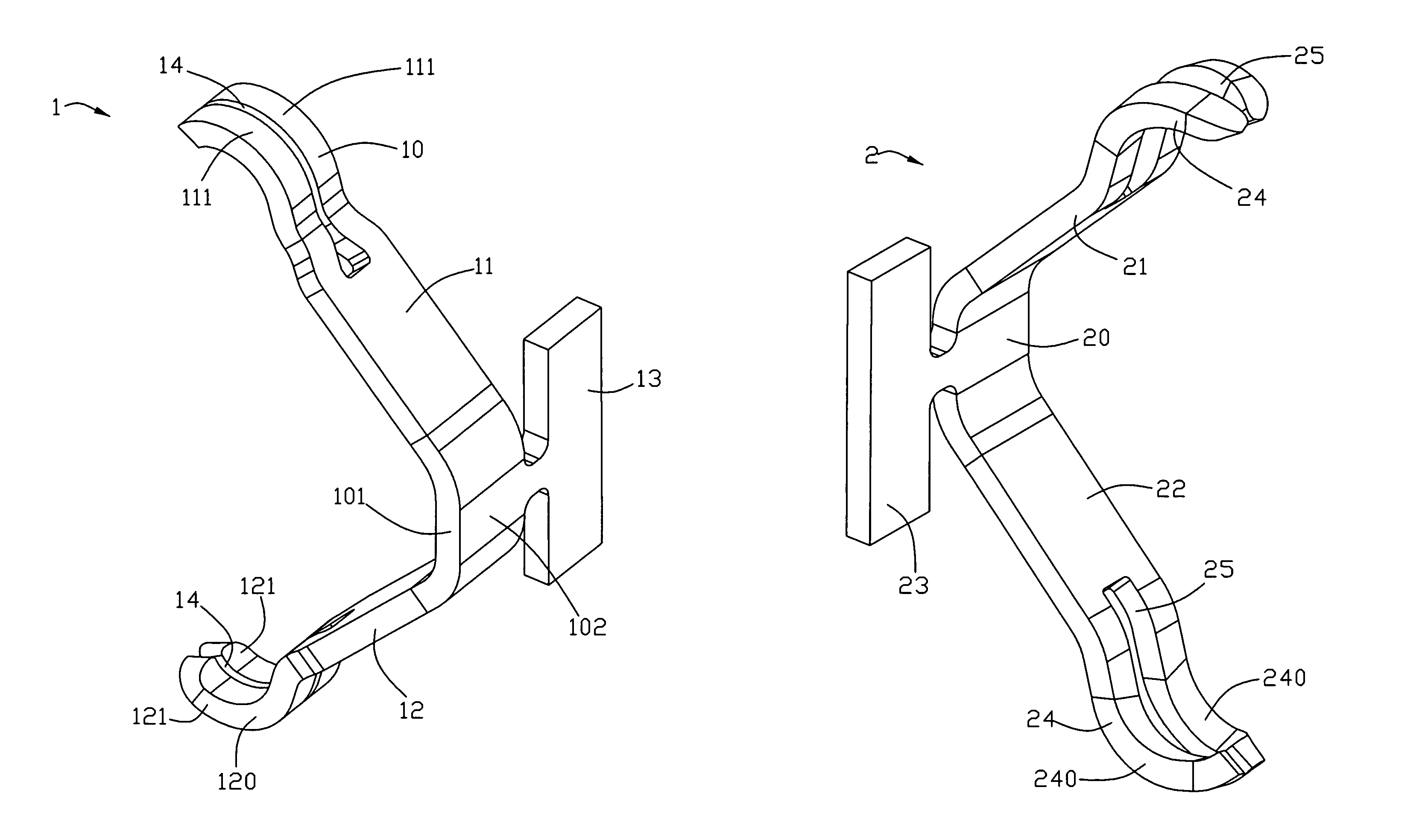
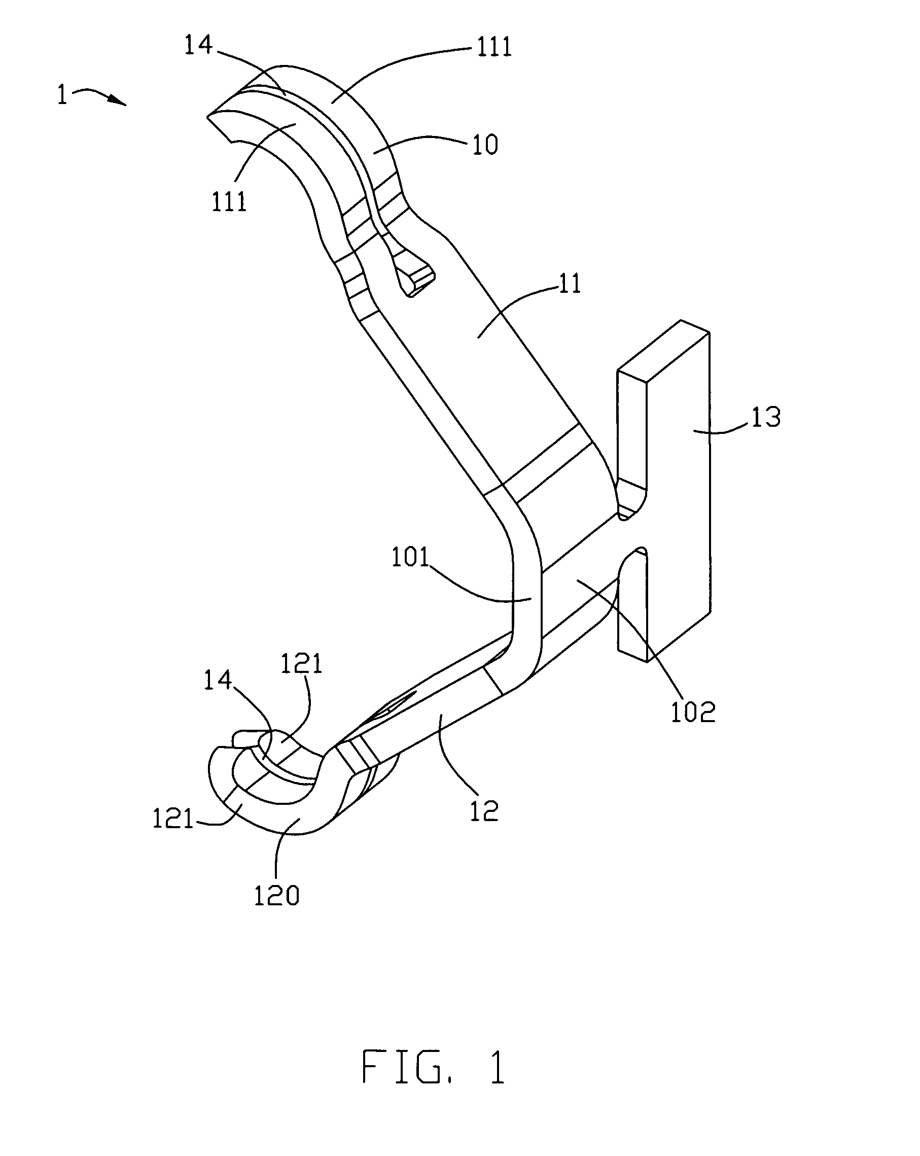
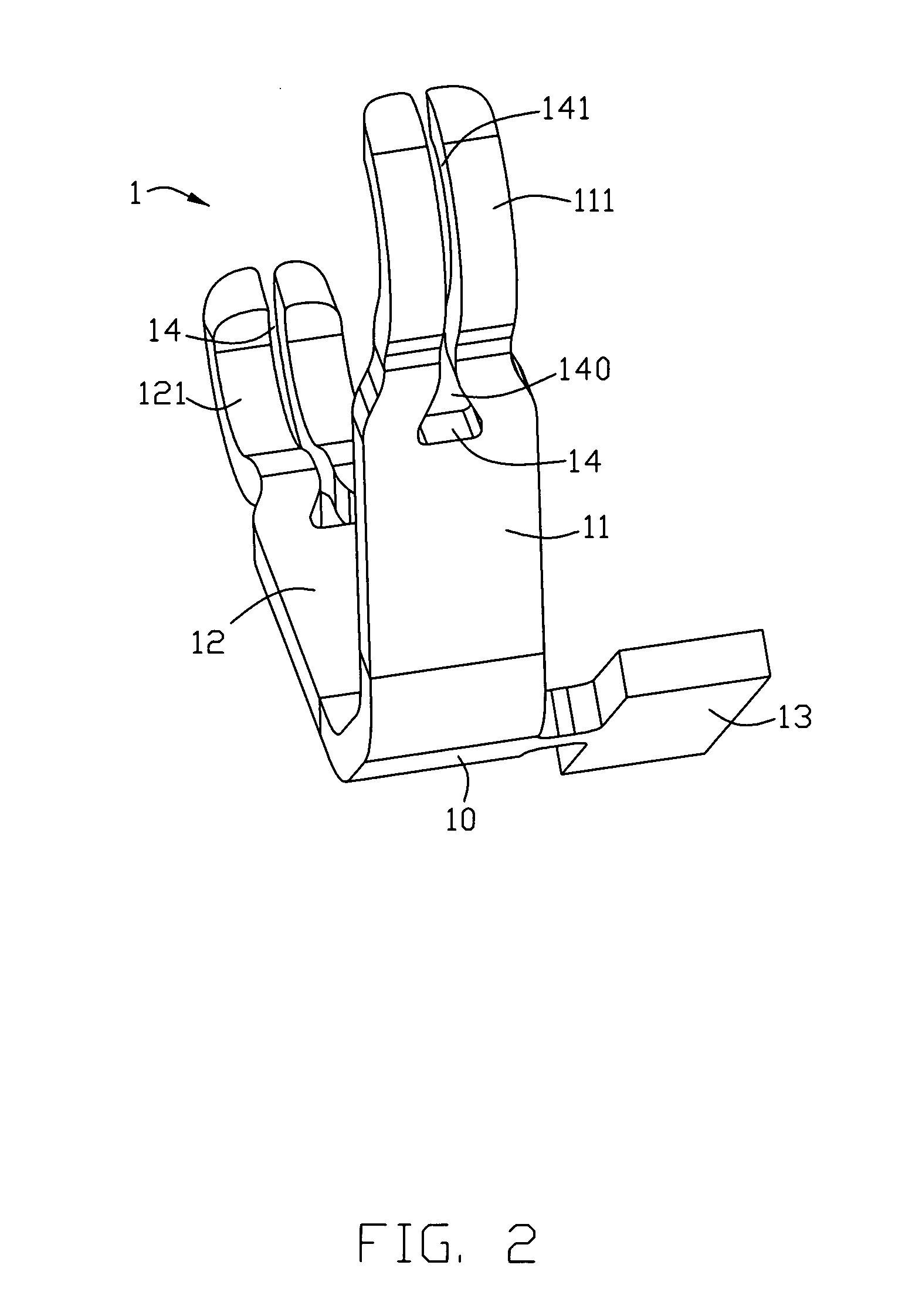
[0015]Referring to FIGS. 1-2, a terminal 1 in accordance with a first preferred embodiment of present invention is disclosed. The terminal 1 is adapted for electrically connecting an IC package (not shown) and a printed circuit board (not shown) by LGA (Land Grid Array) to LGA interface. The terminal 1 comprises a base 10, a first elastic arm 11, a second elastic arm 12 and a retaining portion 13. The base 10 includes a front side 101 and a rear side 102. The first elastic arm 11 laterally and upwardly extends from a top of the base 10. The second elastic arm 12 laterally and downwardly extends from a bottom of the base 10. And a laterally extending direction of the first elastic arm 11 is same with that of the second elastic arm 12, and the first elastic arm 11 and the second elastic arm 12 are face to each other. The retaining portion 13 is rectangle board-like shape and links with the ...


PUM


Abstract

A terminal, adapted for electrically connecting an IC package and a printed circuit board, comprises: a base, a first elastic arm and a second elastic arm. The first elastic arm and the second elastic arm laterally and upwardly extend from a top and a bottom of the base, respectively. Each of the elastic arms has a contact tip on a free end thereof, and each of the two contact tips defines a gap to divide the contact tip into two contacting segments. After the terminal is punched from a metal piece, the gap is inwardly pressed on two sides thereof to have a narrow part between the contacting segments, so a width of the contact tip is reduce.

Description

BACKGROUND OF THE INVENTION[0001]1. Field of the Invention[0002]The present invention relates to a terminal of a socket which is mounted to a printed circuit board and adapted for electrically connecting a semiconductor package, especially to a land grid array (LGA) contact.[0003]2. Description of the Related Art[0004]LGA (Land Grid Array) is one of most common package for IC (Integrated circuit) or wafer. A LGA connector provides a solderless interconnection with a PCB (Printed Circuit Board). Such an electronic connector adapted to a LGA package generally comprises an insulative housing, wherein has a plurality of passageways, in which a plurality terminals are mounted respectively. Each terminal has a pair of electronic contact portions for electrically connecting with a CPU (Central Processing Central) and a PCB respectively. And, both of a bottom surface of the CPU and an upper surface of the PCB are respectively provided a plurality of pads to implement electronic interconnect...

Claims


Application Information

Patent Timeline
IPC IPC(8): H01R4/48H01R12/55
CPCH01R4/4809H01R12/714H01R43/16H01R13/24
Inventor POLNYI, IGOR
Owner HON HAI PRECISION IND CO LTD
Why Eureka
Try Eureka