

Process for manufacture of fluorinated olefins
a technology of fluorinated olefins and manufacturing processes, which is applied in the direction of hydrocarbon preparation catalysts, hydrogen halide split-off preparations, halogenated hydrocarbon preparations, etc., can solve the problems of disadvantages, ineffectiveness and/or economics of the above-mentioned process
- Summary
- Abstract
- Description
- Claims
- Application Information
AI Technical Summary
Benefits of technology
Problems solved by technology
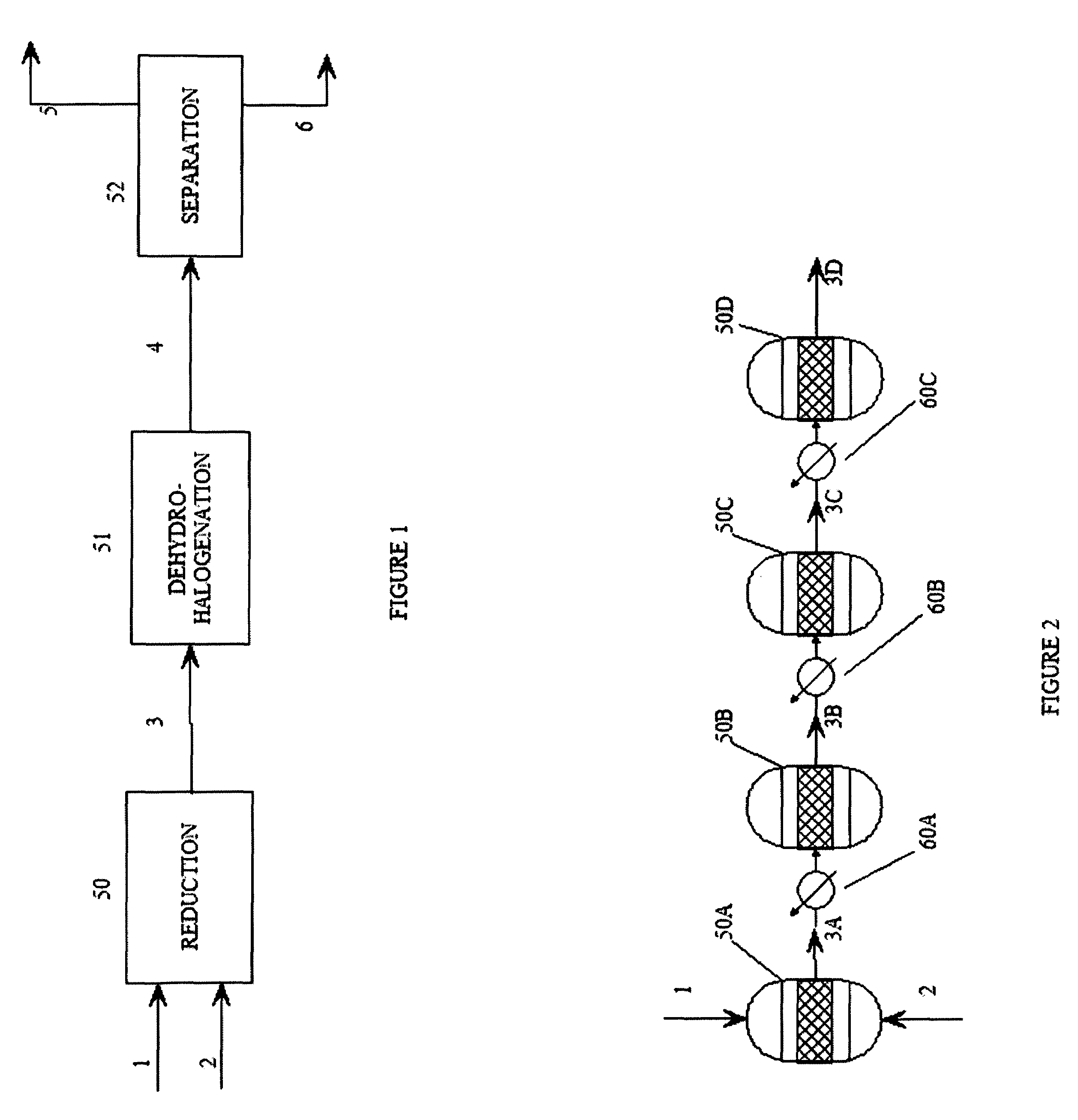
Method used
Image

Examples
examples 1 and 2
Multi-Stage Reduction Reactions
[0060]The reactors used in the following examples are multi-stage reactors constructed from sections of 1.5″ schedule 40, 316 SS pipe.
[0061]The amount of catalyst used to charge each reaction stage is calculated by first estimating the productivity of the catalyst (grams of feed converted per gram of catalyst per hour). The productivity is estimated from scoping studies using a small reactor. Next, the desired production rate is set at about 10 lb per hour, allowing the total amount of catalyst needed for 100% conversion to be estimated. Using this information, an estimated amount of catalyst needed to convert 10-15% of the olefin in the first reactor is calculated.
[0062]Catalyst loading in the following examples is as follows:
[0063]Section 1 (1.5″×1 foot): 10 g of catalyst (1 wt % Pd on 4-8 mesh carbon) with the remainder filled with ¼ SS protruded packing, catalyst equally distributed throughout.
[0064]Section 2 (1.5″×2 foot): 25 g catalyst distribute...
example 1
Multi-stage Reduction of Hexafluoropropene
[0067]Hexafluoropropene is introduced to the multi-stage reactor and reduced continuously over a period of 58 hours during which the average feed rate is 14.5 lb / h (or about 16.4 L per minute). The average hydrogen feed rate is 25 L per minute. Samples are taken at various points along the series of reactors to follow the percent conversion and selectivity. After the second reaction stage, the conversion is about 40%; after the fourth reaction stage, the conversion is 99.5% with selectivity for CF3CHFCF2H of 99%. The temperature of the gases immediately exiting the reaction stages is 66° C. for the first stage, 104° C. for the second stage, 173° C. for the third stage, and 100 C for the fourth stage. The maximum temperature in any reaction stage is about 230° C. The first bath is maintained at 55° C. while the second bath is maintained at 111° C.
example 2
Multi-Stage Reduction of 1,2,3,3,3-Pentafluoropropene-1
[0068]1,2,3,3,3-Pentafluoropropene-1 is hydrogenated using the same reactor as in Example 1 using a feed rate of 14.6 lb / h for a total of 64 hours. The average hydrogen feed rate is 25 liters per minute. Samples are taken at various points along the series of reactors to follow the percent conversion and selectivity. After the second reactor, the conversion is about 54%. While after the fourth reactor, the conversion is 100% with the selectivity for CF3CHFCH2F of 98%. The temperature of the gases immediately exiting the reactors is 99° C. for the first reactor, 95° C. for the second reactor, 173° C. for the third reactor, and 104° C. for the fourth reactor. The maximum temperature in any reactor is about 240° C. The first bath is maintained at 59° C., and the second bath is maintained at 116° C.
PUM
| Property | Measurement | Unit |
|---|---|---|
| temperature | aaaaa | aaaaa |
| temperature | aaaaa | aaaaa |
| temperature | aaaaa | aaaaa |
Abstract
Description
Claims
Application Information