Rotation angle using orthogonal magnetic sensing elements in close proximity to each other

a magnetic sensing element and orthogonal technology, applied in the direction of galvano-magnetic devices, galvano-magnetic hall-effect devices, instruments, etc., can solve the problems of temperature difference between the setting direction of two magnetic sensing elements may not be desired, and the difficulty in accurately positioning the magnetic sensing elements, etc., to achieve the effect of accurately detecting the rotation angle of a rotating object and improving the rotation angle detecting

Inactive Publication Date: 2009-07-14
DENSO CORP +1
View PDF10 Cites 7 Cited by
  • Summary
  • Abstract
  • Description
  • Claims
  • Application Information

AI Technical Summary

Benefits of technology

[0007]Therefore, an object of the invention is to provide an improved rotation angle detecting device that can accurately detect the rotation angle of a rotating object.
[0010]Because the two magnetic sensing elements are disposed very close to each other, it is possible to integrate them into a unit, so that the angle between the two elements and the setting directions thereof may be accurately formed. In addition, there is little temperature difference between two hall elements.

Problems solved by technology

Because the magnetic sensing elements are spaced apart in the rotating direction, it is difficult to accurately position the magnetic sensing elements.
In other words, the angle formed between two magnetic sensing elements may not be a desired angle, the setting directions of two magnetic sensing elements may not be desired directions, or temperature difference between two magnetic sensing elements may arise.
As a result, the magnetic sensing elements may generate signals that may cause an error in the rotation angle to be detected.

Method used


Image

  • Rotation angle using orthogonal magnetic sensing elements in close proximity to each other
  • Rotation angle using orthogonal magnetic sensing elements in close proximity to each other
  • Rotation angle using orthogonal magnetic sensing elements in close proximity to each other

Examples


first embodiment

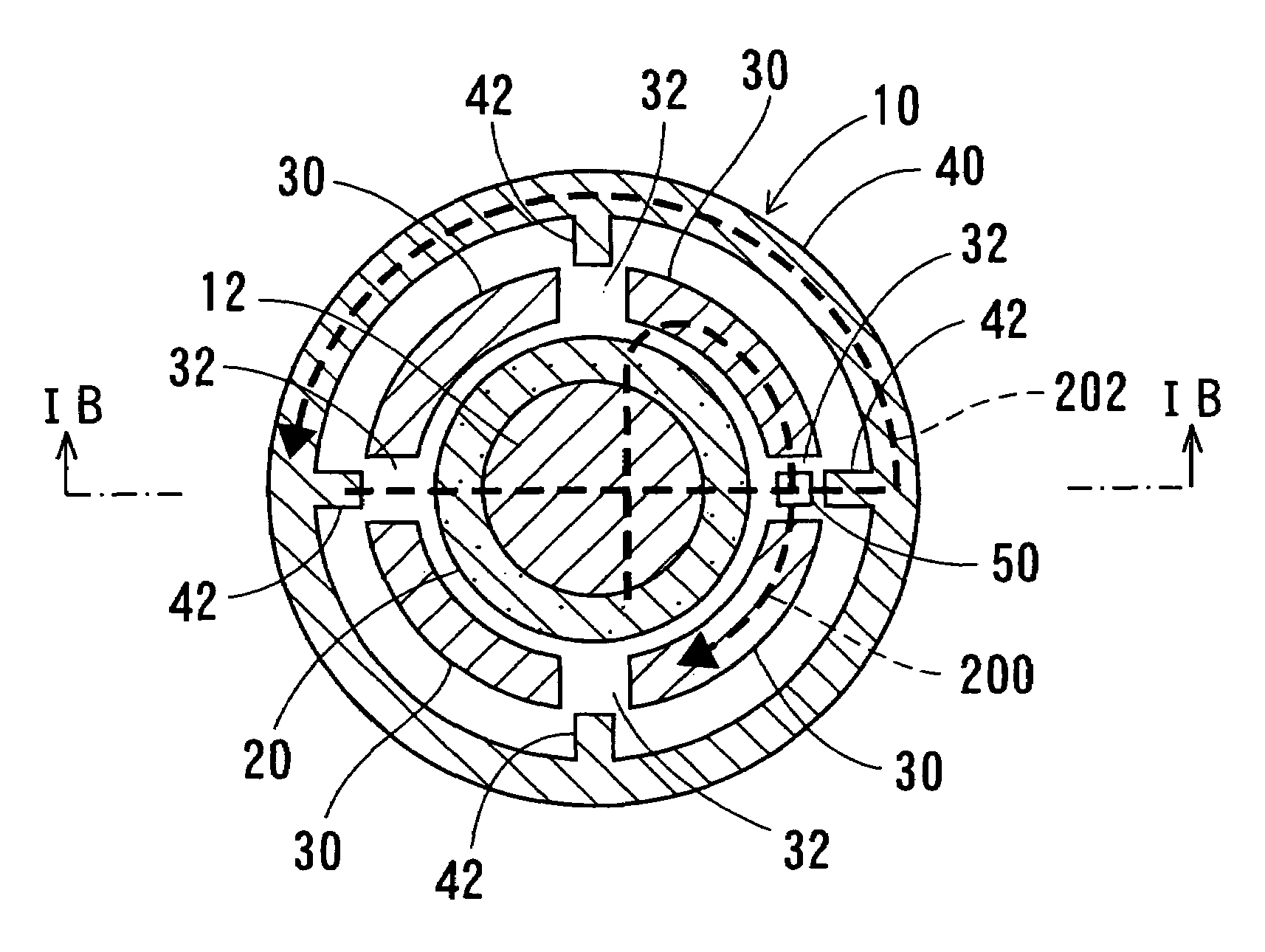
[0029]A rotation angle detecting device according to the invention will be described with reference to FIGS. 1A-3.

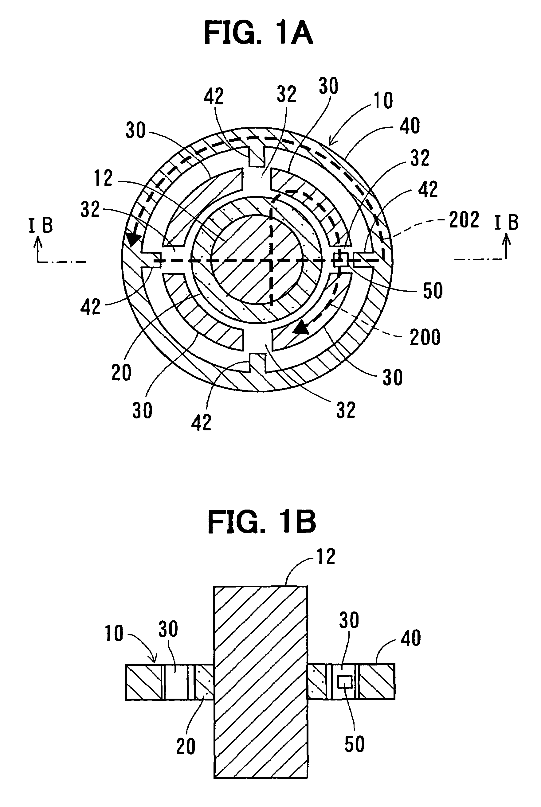
[0030]As shown in FIGS. 1A and 1B, a rotation angle detecting device 10 is set around a rotary shaft 12 that is linked with a rotating object (not shown). The rotation angle detecting device 10 is constituted of a ring-shaped permanent magnet 20, four arc-shaped magnetic inner yokes 30, a generally cylindrical magnetic outer yoke 40 and a magnetic sensor 50.

[0031]The ring-shaped permanent magnet 20 is magnetized to polarize in parallel with a radial direction thereof and fixed to the circumference of the rotary shaft 12. The four inner yokes 30 are disposed around the permanent magnet 20 at equal intervals so that gaps 32 can be formed at intervals of 90 degrees. In other words, each of the gaps 32 is positioned around the permanent magnet 20 opposite to, or at 180 degrees from, another of the gaps 32. The cylindrical outer yoke 40 is disposed around the inner yokes 30. ...

second embodiment

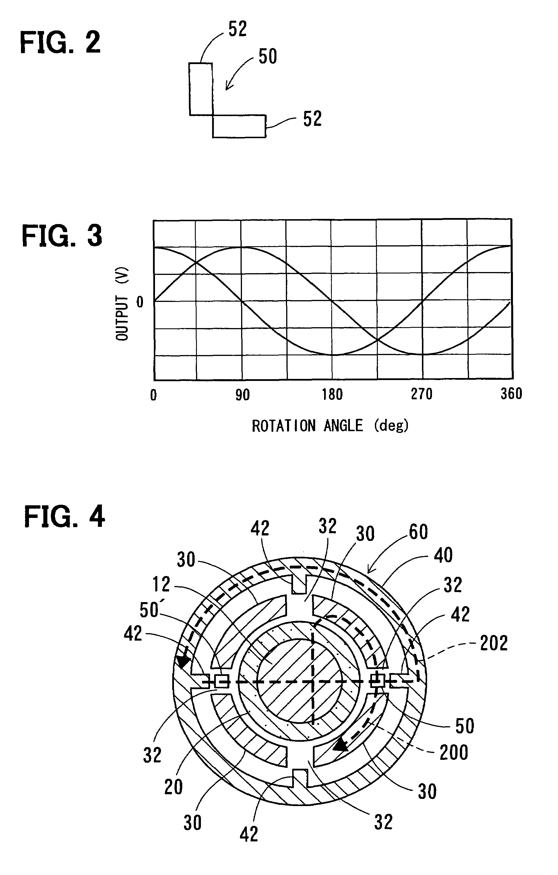
[0037]A rotation angle detecting device 60 will be described with reference to FIG. 4. Incidentally, the same reference numeral indicates the same or substantially the same part, portion or component hereafter.

[0038]As shown in FIG. 4, one more magnetic sensor 50′ is disposed in another gap 32 that is located 180 degrees from the first magnetic sensor 50. With this additional magnetic sensor 50′, a variation in the output signal of each of the magnetic sensors 50, 50′ can be easily corrected by combining the output signals of both magnetic sensor 50 and the magnetic sensor 50′. The additional magnetic sensor may be disposed in a gap other than 180 degrees from the first magnetic sensor 50. Two or more additional sensors may be also used.

third embodiment

[0039]A rotation angle detecting device 70 will be described with reference to FIG. 5.

[0040]The rotation angle detecting device 70 is constituted of two pieces of arc-shaped inner yokes 72 and an outer yoke 76 having two projections 78 to provide a pair of gaps 74 so as to be positioned around the permanent magnet 20 opposite to, or at 180 degrees from, the other, instead of four pieces of arc-shaped inner yokes 30 of the first embodiment and the outer yoke 40 having four projections 42 thereof. The inner yokes 72 and the outer yoke 76 with one of the projections 78 confronting the magnetic sensor 50 form magnetic paths 200, 202 to cross each other at the sensor 50 at an angle of 90 degrees, as illustrated by broken lines.

[0041]It is easier to assemble the inner yokes 72 than the first embodiment.


PUM


Abstract

A rotation angle detecting device that detects a rotation angle of a rotating object includes a permanent magnet that generates magnetic fields in response to rotation of the rotating object, a magnetic sensor, a first yoke and a second yoke. The magnetic sensor includes a pair of close integrated magnetic sensing elements, such as hall elements, disposed at a position around the permanent magnet so that one of the sensing elements senses magnetic field at a phase different from the other. The first yoke and the second yoke forms two magnetic paths crossing each other at the magnetic sensor.

Description

CROSS REFERENCE TO RELATED APPLICATION[0001]The present application is based on and claims priority from Japanese Patent Application 2005-283939, filed Sep. 29, 2005, the contents of which are incorporated herein by reference.BACKGROUND OF THE INVENTION[0002]1. Field of the Invention[0003]The present invention relates to a rotation angle detecting device that detects a rotation angle of an rotating object.[0004]2. Description of the Related Art[0005]Usually, a rotation angle of a rotating object is detected by a rotation angle detecting device that is constituted of a permanent magnet rotor linked with the rotating object, a pair of magnetic sensing elements that are respectively disposed around the permanent magnet rotor to be spaced apart from each other in the rotating direction, as disclosed in JP-A-2004-271495 or, its counterpart, US 2004 / 0164733 A1. When the rotating object rotates, the magnetic sensing elements detect a change in a magnetic field that is generated by the perm...

Claims


Application Information

Patent Timeline
Patent Type & Authority Patents(United States)
IPC IPC(8): G01B7/30
CPCG01D5/145G01D2205/40
Inventor HATANAKA, SHINJITAKEDA, KENJINAKAMURA, TSUTOMUSHIMOMURA, OSAMUKAWASHIMA, TAKASHIMATSUMOTO, KOICHIRO
Owner DENSO CORP
Why Eureka
Try Eureka