Electroluminescent data cable identification and computer system diagnostics

a technology of electrically conductive data and computer system, applied in the field of visual identification of data cables, can solve problems such as transmission errors, unexpectedly large voltage or temperature rise, and faults that may occur with such connections, and achieve the effect of improving cable identification and diagnostic capabilities

Active Publication Date: 2009-07-14
LENOVO GLOBAL TECH INT LTD
View PDF10 Cites 7 Cited by
  • Summary
  • Abstract
  • Description
  • Claims
  • Application Information

AI Technical Summary

Problems solved by technology

Still, a variety of faults may occur with such connections.
Examples of faults include an “open pin” condition, an unexpectedly large voltage or temperature rise, or a data transmission error.
Troubleshooting the connections in such computer systems can therefore be challenging.
However, conventional diagnostic systems are not without some disadvantages.
For example, individually identifying a faulty data cable, connection, or connection port can be difficult where numerous data cables are closely grouped.
However, color coding is limited to the relatively few colors that can be easily distinguished by the human eye.
The color of cable housings may also be difficult to discern in dim lighting, which is common when cables are routed behind or between equipment.
Still, the LEDs on the ends of a cable do not allow a user to see the entire path of the cable routing and a user's view of the ends of the cable may be obscured by a server rack, component chassis, or other structure.

Method used


Image

  • Electroluminescent data cable identification and computer system diagnostics
  • Electroluminescent data cable identification and computer system diagnostics
  • Electroluminescent data cable identification and computer system diagnostics

Examples


Embodiment Construction

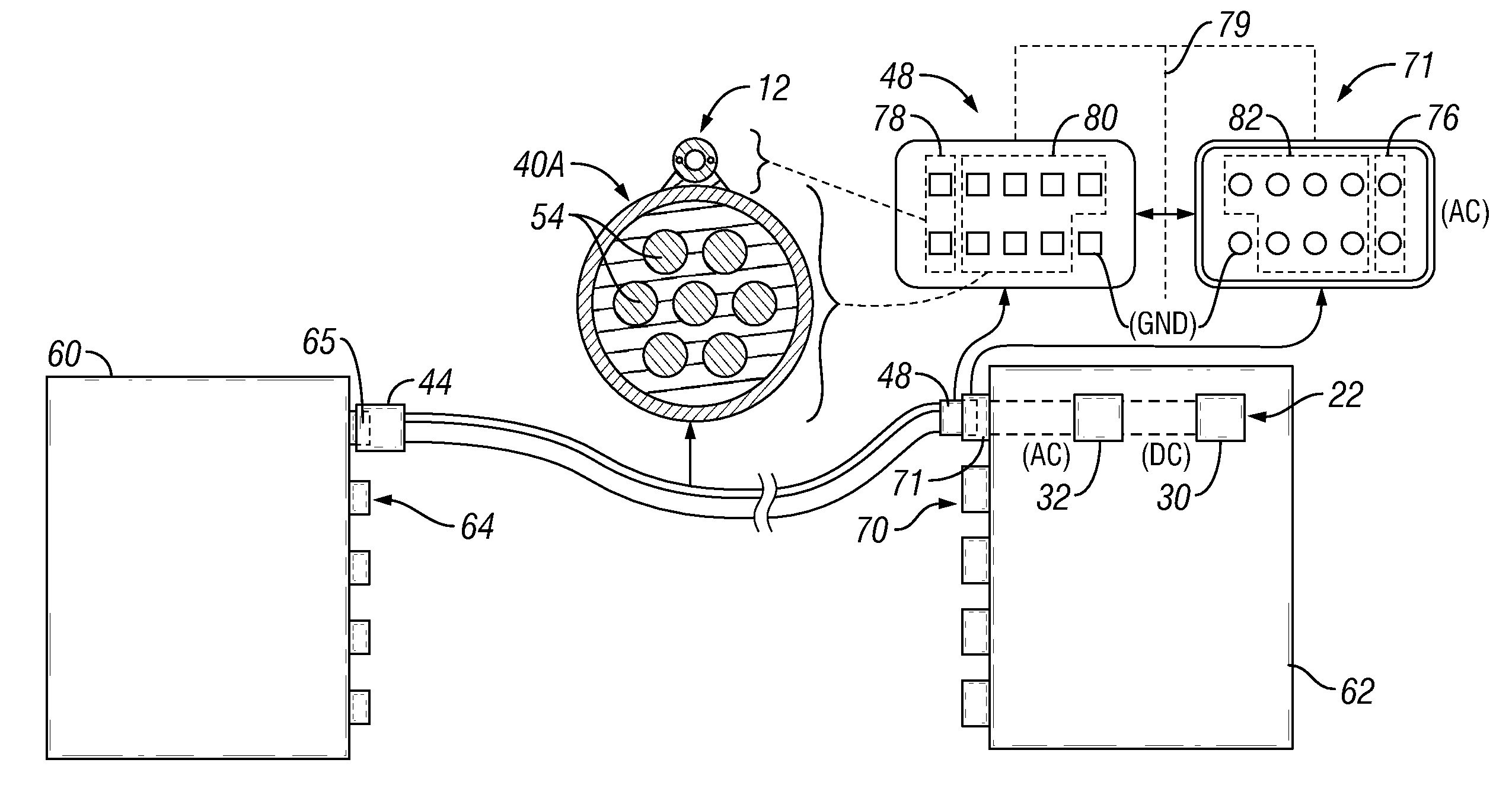
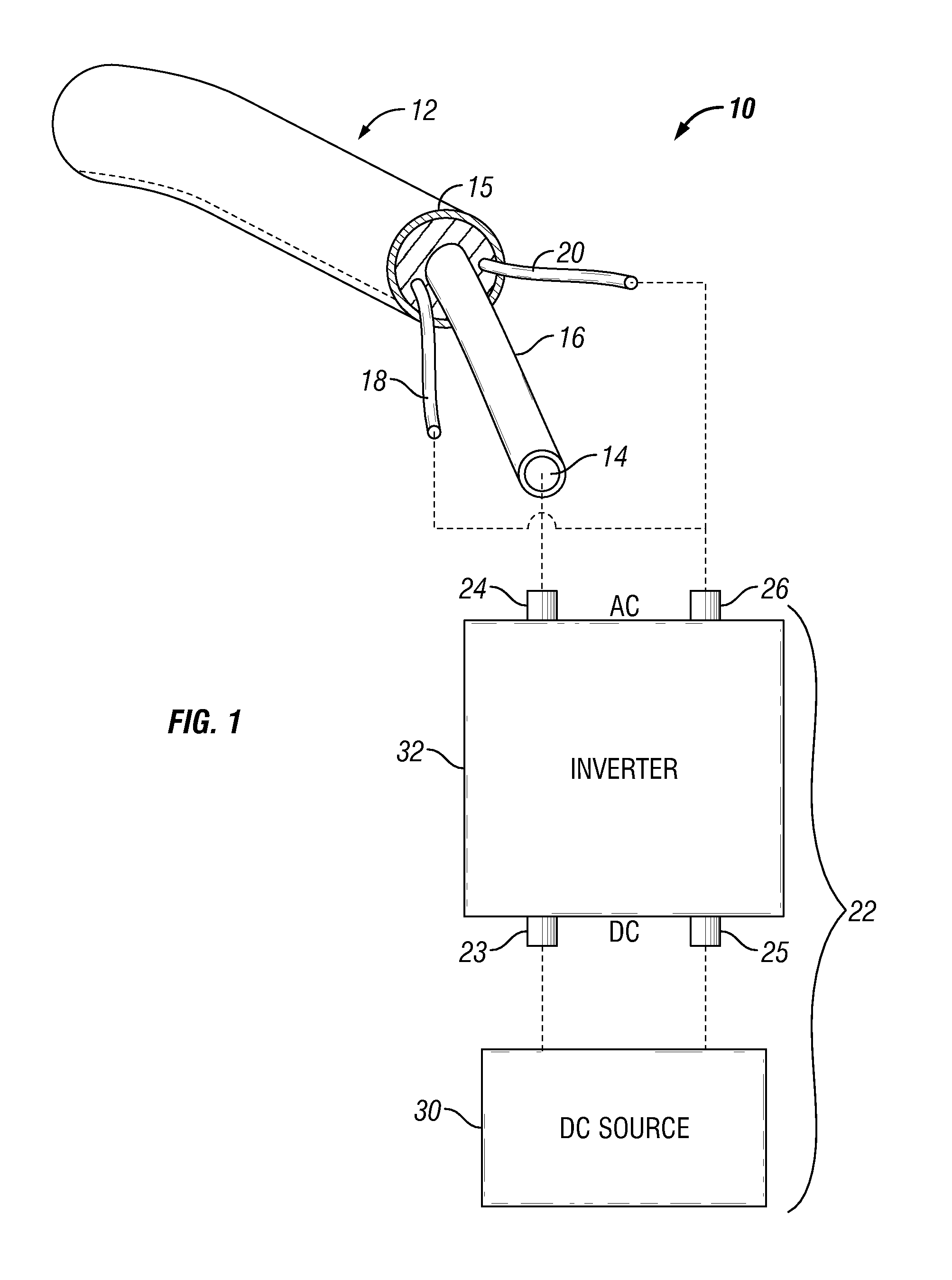
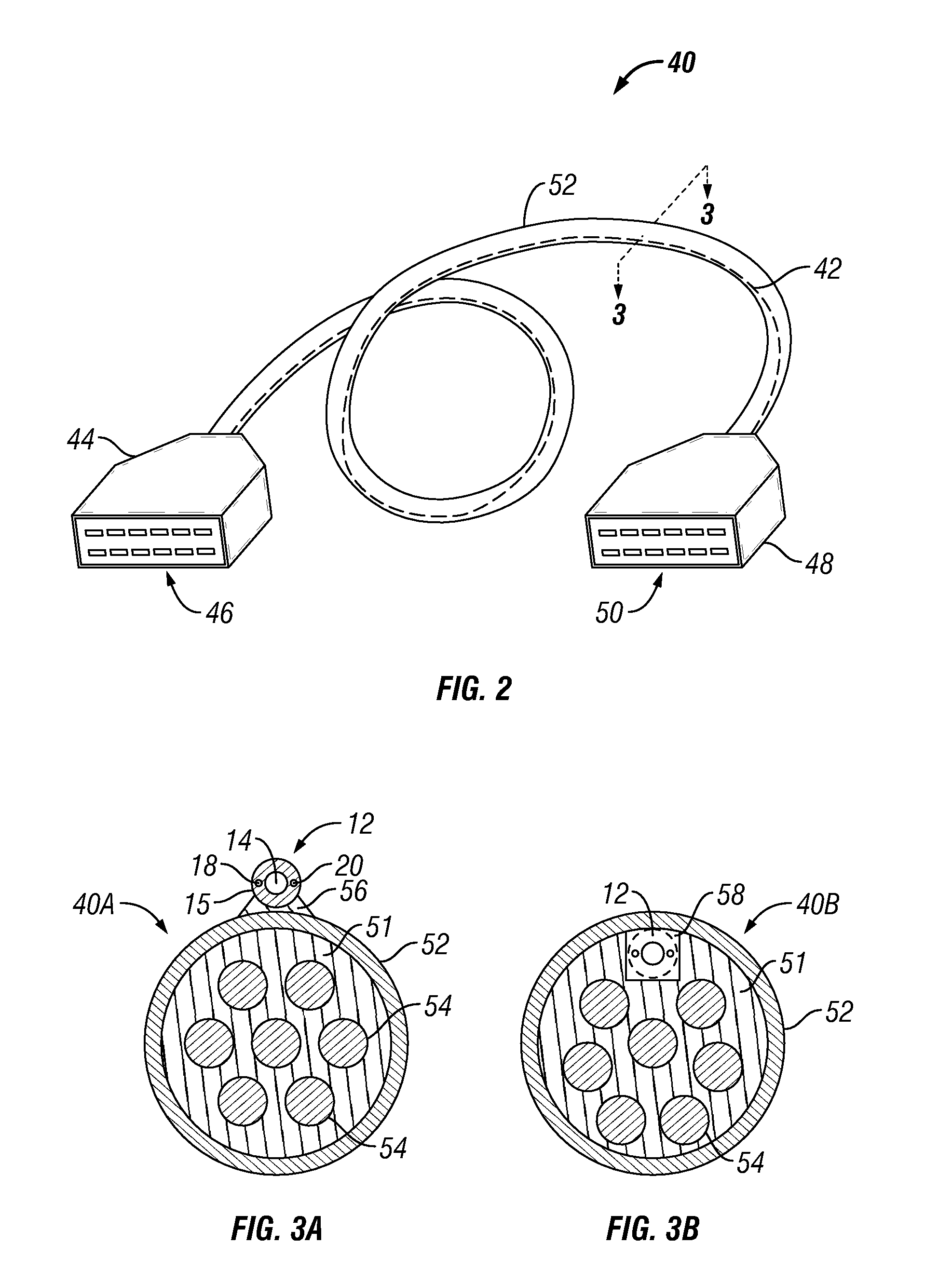
[0018]The present invention utilizes electroluminescence technology to provide improved diagnostics and cable identification in computer system connections. In one embodiment, a data cable for data communication between two electronic devices includes an electroluminescent (EL) strand or cable along its length. The EL strand may be attached to the outer side of the data cable housing, or routed inside a transparent or translucent data cable housing. An electronically insulating material disposed within the cable housing for insulating between the plurality of wires and the electroluminescent strand may be selected from an aluminum foil, mylar foil, tinned copper braid, and combinations thereof. The data cable typically has a first connector at one end for plugging into a mating connector on a first electronic device, such as a first server, and a second connector at the other end for plugging into a mating connector on a second electronic device, such as a second server. The first a...


PUM


Abstract

Cable identification and computer system diagnostics are facilitated with electroluminescent technology. In one embodiment, a computer data cable includes an electroluminescent strand having a first wire with an electroluminescent coating and a second wire in contact with the inner wire. An AC voltage is applied between the inner and outer wire to selectively illuminate the electroluminescent strand in response to predetermined conditions, such as in response to the detection of a connection-related fault or in response to plugging in the data cable to a device port. Diagnostic techniques such as FMEA may be implemented in software for detecting connection faults and selectively illuminating the data cables in response.

Description

BACKGROUND OF THE INVENTION[0001]1. Field of the Invention[0002]The present invention relates both to the visual identification of data cables and the diagnosis of connection faults in computer systems.[0003]2. Description of the Related Art[0004]Computer systems typically include multiple electronic components interconnected with cables. In a rack-based server system, for example, multiple servers and other devices may be interconnected to achieve scalability. Each server or other device to be interconnected generally includes a plurality of connection ports. Data cables are typically used to connect the connection ports of one server with the connection ports of another server. Still, a variety of faults may occur with such connections. Examples of faults include an “open pin” condition, an unexpectedly large voltage or temperature rise, or a data transmission error. The occurrence of a fault is particularly likely where multiple connections are involved. For example, rack-based s...

Claims


Application Information

Patent Timeline
Patent Type & Authority Patents(United States)
IPC IPC(8): G08B3/00
CPCH01B7/32G02B6/3895
Inventor DUFFY, III, WILLIAM R.SASS, TONY CARL
Owner LENOVO GLOBAL TECH INT LTD
Why Eureka
Try Eureka