Fixing structure

a fixing structure and structure technology, applied in the direction of furniture parts, instruments, cabinet casings/cabinets/drawers of electric apparatus, etc., can solve the problems of easy loss of screws, large inconvenience, and a lot of trouble for operators, so as to prevent deformation by external forces and enhance the structural strength of the fixing structure

Inactive Publication Date: 2009-07-14
INVENTEC CORP
View PDF10 Cites 18 Cited by
  • Summary
  • Abstract
  • Description
  • Claims
  • Application Information

AI Technical Summary

Benefits of technology

[0007]Therefore, the fixing structure, when under an external force, can be moved between the retaining portion and the first support plate of the frame, within spaces provided by the first opening and the second opening, by the resilience of the resilient element. When an operator installs an electronic peripheral (such as an optical disk drive or a hard disk drive, etc.) between the first latch plate of the frame and the second latch plate of the fixing structure, the fixing structure can be resiliently moved toward the first latch plate, so that the second latch plate and the first latch plate cooperate to clamp and secure the electronic peripheral. If the operator moves the fixing structure away from the first latch plate, the second latch plate will be separated from the electronic peripheral, so as to release the electronic peripheral. As a result, the operator can speedily and easily install or remove the electronic peripheral on / from the frame.
[0008]A secondary objective of the present invention is to provide a fixing structure as mentioned above, wherein the board is further formed with an engagement plate between the second support plate and the bearing plate. When the operator rotates the resilient element to a predetermined position, the resilient element will be engaged with the engagement plate and, therefore, prevented from being deformed by an external force. After the electronic peripheral is installed, the engagement between the resilient element and the engagement plate can effectively prevent the fixing structure from being pushed by the electronic peripheral pushing under an improper external force (such as a shaking caused by an accidental impact), so that the resilient element will not be deformed, and the fixing structure, therefore, will not move away from the first latch plate to disengage the electronic peripheral from the frame and the fixing structure.
[0009]A third objective of the present invention is to provide a fixing structure as mentioned above, wherein the board further has another two opposite sides, and the another two opposite sides each is formed with a reinforced flange. As a result, when the fixing structure is moved toward the first latch plate by the resilience of the resilient element to fix the electronic peripheral, a portion of the board between the resilient element and the electronic peripheral can bear a continuous pressure from the resilient element pushing the board toward the electronic peripheral. The reinforced flanges can substantially enhance the structural strength of the fixing structure, so as to prevent the fixing structure from being deformed by the pressure.

Problems solved by technology

Because of their small sizes, the screws are not only difficult to fasten and unscrew, but also get lost easily after being unscrewed.
This may complicate the procedures for installing or removing the electronic peripheral on / from the frame, causing considerable inconvenience and creating a lot of troubles to the operator.
As a result, the assembling or disassembling speed cannot be efficiently enhanced.

Method used


Image

  • Fixing structure
  • Fixing structure
  • Fixing structure

Examples


Embodiment Construction

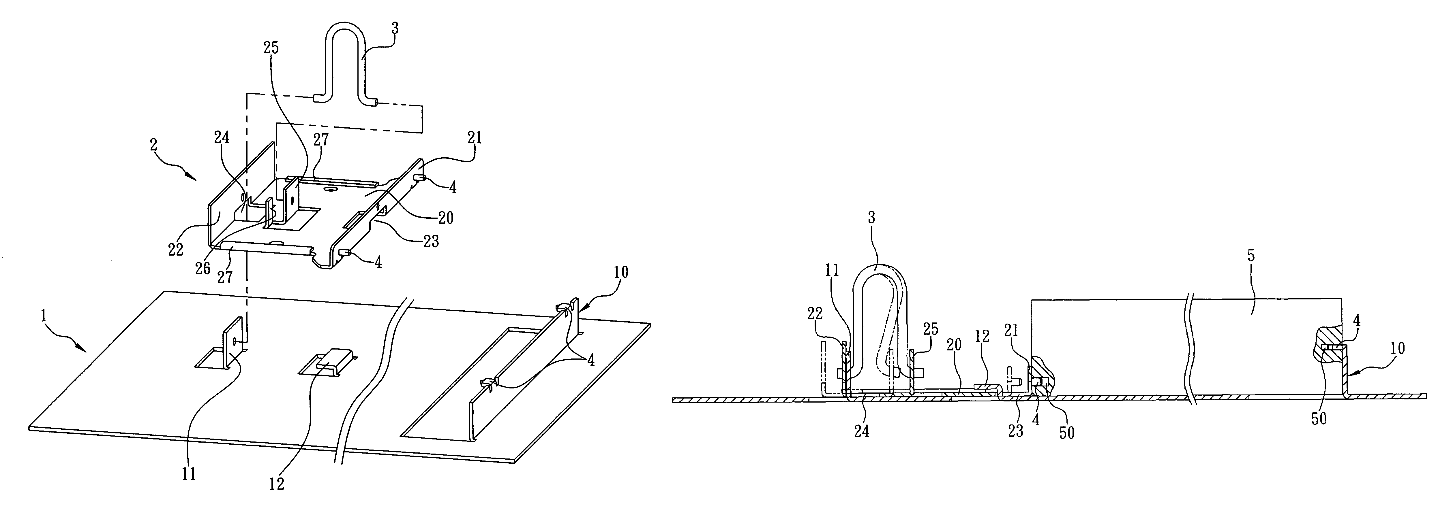
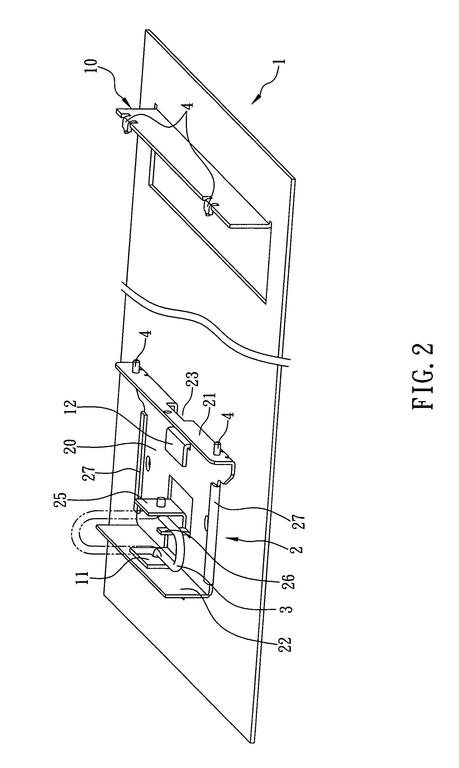
[0014]FIG. 1 illustrates a fixing structure 2 according to a preferred embodiment of the present invention. As shown in FIG. 1, the fixing structure 2 is applied to a frame 1 which has a surface vertically formed with a first latch plate 10 and a first support plate 11, wherein the first latch plate 10 and the first support plate 11 are parallel to each other. Meanwhile, the surface of the frame 1 is further formed with a retaining portion 12 between the first latch plate 10 and the first support plate 11. The fixing structure 2 comprises a board 20 having a second latch plate 21 vertically extending from one side, and a bearing plate 22 vertically extending from the other side opposite to the side formed with the second latch plate 21. Furthermore, a first opening 23 is formed on an abutting position between the second latch plate 21 and the board, while a second opening 24 is formed on another abutting position between the bearing plate 22 and the board 20. Moreover, the board 20 ...


PUM


Abstract

The present invention discloses a fixing structure applicable to a frame, wherein a first latch plate and a first support plate parallel to each other are disposed vertically on the frame. The fixing structure includes a board, a second latch plate disposed on a surface of the board, and a second support plate parallel to the second latch plate disposed on the board. When the fixing structure is placed on the surface of the frame, the first support plate is passed through a second opening of the fixing structure. A resilient element is pivotally coupled between the first support plate and the second support plate, such that the fixing structure can be moved on the frame by the resilience of the resilient element, enabling an operator to easily install or remove an electronic peripheral on or from the space between the first and second latch plates of the frame.

Description

FIELD OF THE INVENTION[0001]The present invention relates to a fixing structure, and more particularly to a fixing structure applicable to a frame of a computer equipment for enabling an operator to speedily and easily install or remove an electronic peripheral (such as an optical disk drive or a hard disk drive, etc.) on or from the frame.BACKGROUND OF THE INVENTION[0002]Recently, with the development of computer technologies, functions of computer equipments are continuously increased and improved, while the market price thereof is lower day by day. Thus, computer equipments have become affordable consumer products, or even indispensably important tools, in our daily life and work. In response to the heated competition in the computer market, various design houses and manufacturers of computer equipments have made great efforts to simplify the manufacturing processes and mechanism designs of computer equipments in order to effectively reduce the time and manpower required for inst...

Claims


Application Information

Patent Timeline
Patent Type & Authority Patents(United States)
IPC IPC(8): H05K7/12
CPCG11B33/12G06F1/187Y10T292/1052
Inventor CHANG, LIN-WEI
Owner INVENTEC CORP
Why Eureka
Try Eureka