
Nuclear fuel spacer assembly with debris guide

a technology of nuclear fuel and spacer, which is applied in the direction of nuclear elements, nuclear engineering problems, greenhouse gas reduction, etc., can solve the problems of fuel assembly damage, fuel rod tube perforation, and chip and metal particles still hidden, so as to increase the probability

Active Publication Date: 2009-07-14
GLOBAL NUCLEAR FUEL -- AMERICAS
View PDF21 Cites 29 Cited by
  • Summary
  • Abstract
  • Description
  • Claims
  • Application Information

AI Technical Summary

Benefits of technology

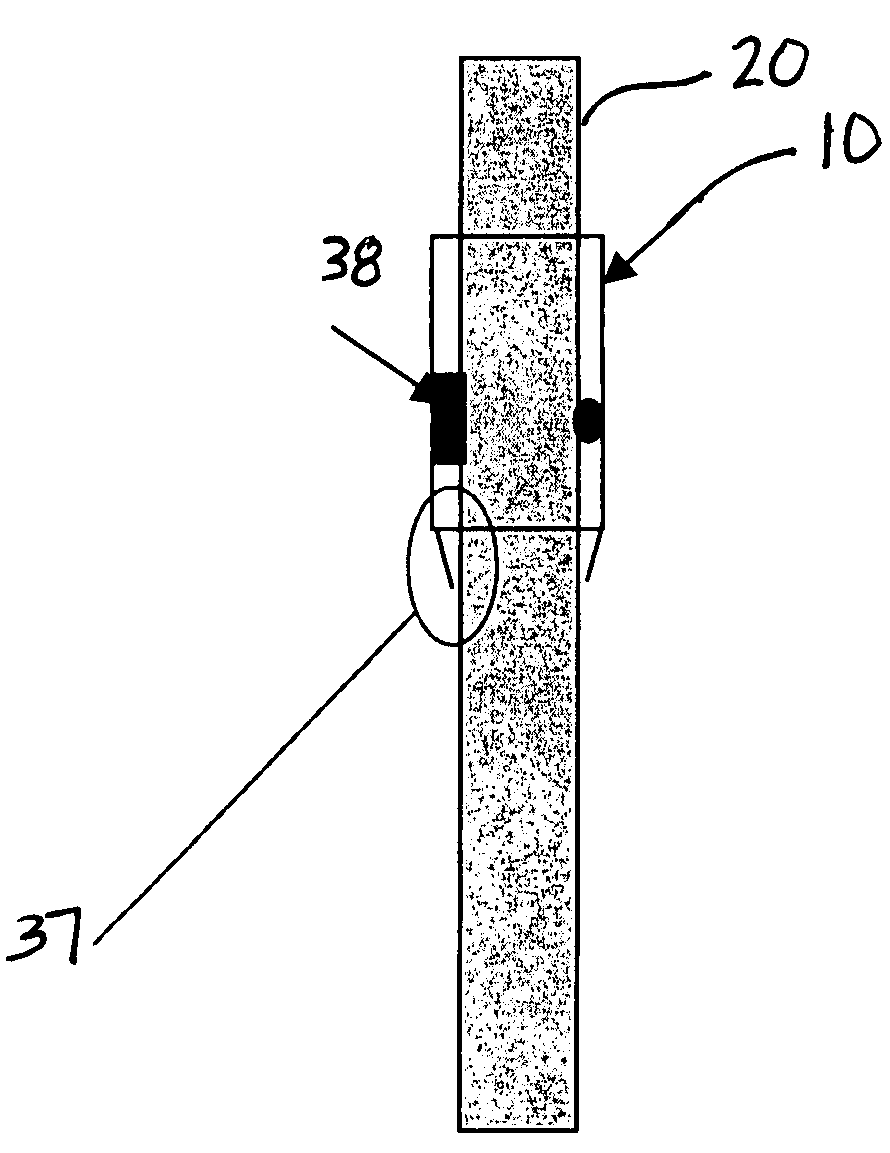
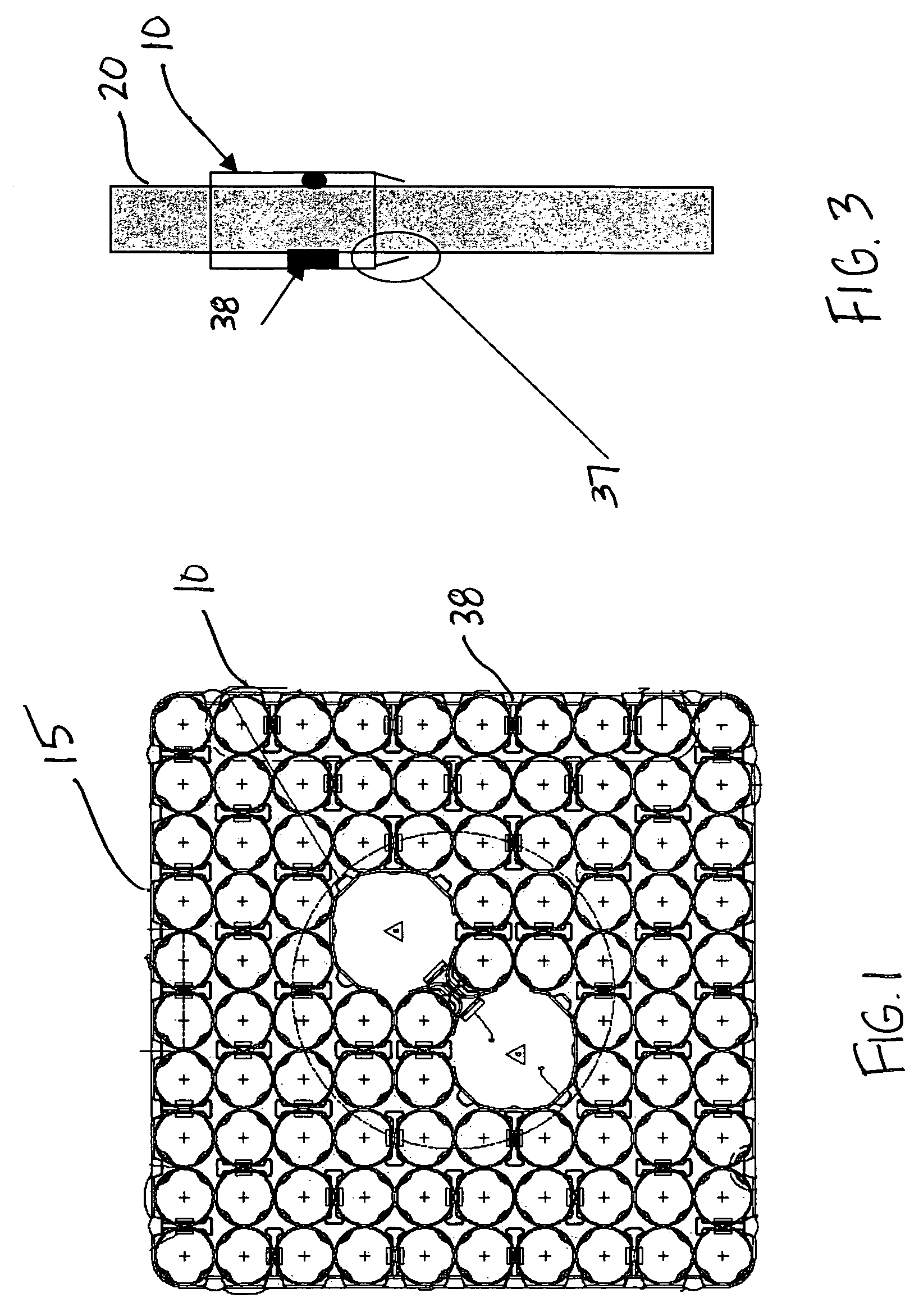
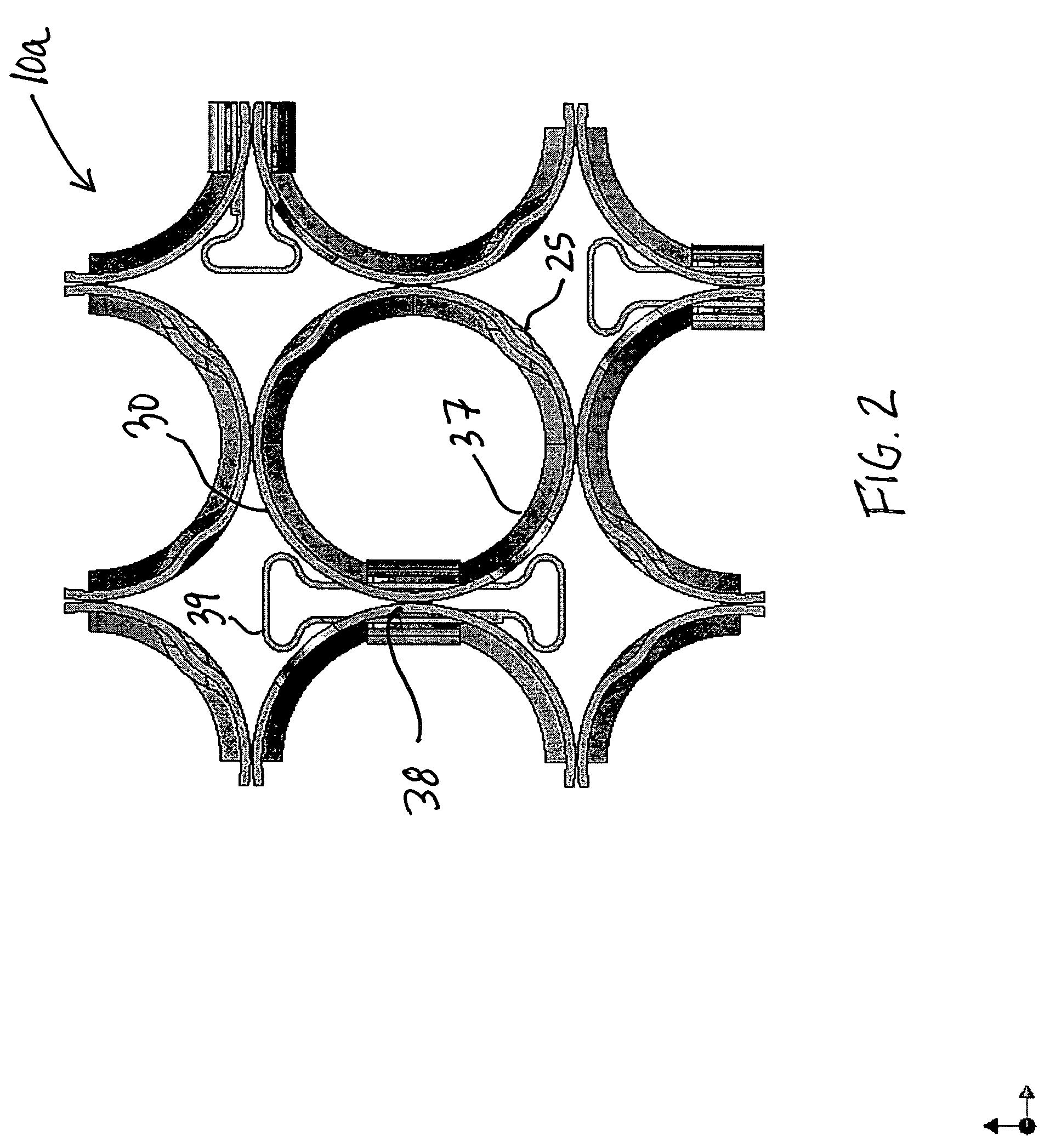
"The present invention is about a fuel assembly for a nuclear reactor that includes a plurality of nuclear fuel rods and at least one fuel rod spacer assembly supporting the fuel rods in an organized array. The fuel rod spacer assembly contains a guide for directing debris to open passages in the assembly. The guide is angled towards the fuel rod and acts to shield horizontal surfaces from the coolant flow with angled members. The guide is designed to preferentially orient debris to present the minimum cross sectional area to increase the probability that it can completely pass through the assembly. The invention also includes specific features or devices to direct debris in the reactor coolant through open spaces in the assembly to reduce the probability of debris being captured and causing a fuel rod failure due to fretting."

Problems solved by technology

Although elaborate procedures are carried out to help assure debris removal, and in spite of the safeguards used to effect such removal, some chips and metal particles still remain hidden in the system.
For example, damage to the fuel assembly may occur due to debris trapped at the fuel rod spacer assembly in reactors.
The damage consists of fuel rod tube perforations caused by fretting of debris in contact with the exterior of the tube.
Although these filtering devices have been effective in filtering out a wide range of debris types and sizes, these conventional filters do not filter all the debris and do not protect debris from entering the fuel bundle, for example, from the top of the bundle
While the conventional approach may operate reasonably well and may generally achieve their objectives under the range of operating conditions for which they were designed, they also create several other problems (e.g., compatibility issue, inconsistent operating cycle, cost, and others.).

Method used


Image

  • Nuclear fuel spacer assembly with debris guide
  • Nuclear fuel spacer assembly with debris guide
  • Nuclear fuel spacer assembly with debris guide

Examples


Embodiment Construction

[0020]It should be noted that these Figures are intended to illustrate the general characteristics of method and apparatus of exemplary embodiments of this invention, for the purpose of the description of such exemplary embodiments herein. These drawings are not, however, to scale and may not precisely reflect the characteristics of any given embodiment, and should not be interpreted as defining or limiting the range of values or properties of exemplary embodiments within the scope of this invention. The relative dimensions and size of a fuel assembly may be reduced or exaggerated for clarity. Like numerals are used for liked and corresponding parts of the various drawings.

[0021]In general, a fuel assembly as described herein may be the type used in a boiling pressurized water reactor. The fuel assembly will typically include fuel rods held in spaced relationship with one another by grids spaced along the fuel assembly length. Each fuel rod includes nuclear fuel pellets (not shown) ...


PUM


Abstract

In a fuel assembly for a nuclear reactor, a plurality of nuclear fuel rods and at least one fuel rod spacer assembly supporting the fuel rods in an organized array. The fuel rod spacer assembly includes a guide at a leading edge of the fuel rod spacer assembly. The guide is angled towards the fuel rod for directing debris to open passages in the fuel rod spacer assembly.

Description

BACKGROUND OF THE INVENTION[0001]1. Field of the Invention[0002]This invention relates generally to a nuclear fuel rod spacer assembly.[0003]2. Description of Related Art[0004]During manufacture and subsequent installation and repair of components comprising a nuclear reactor coolant circulation system, diligent effort is made to assure removal of all debris (e.g., metal chips and shavings, small solid sections of metal, and the like) from the reactor vessel and its associated systems which circulate coolant therethrough under various operating conditions. Although elaborate procedures are carried out to help assure debris removal, and in spite of the safeguards used to effect such removal, some chips and metal particles still remain hidden in the system.[0005]For example, damage to the fuel assembly may occur due to debris trapped at the fuel rod spacer assembly in reactors. The damage consists of fuel rod tube perforations caused by fretting of debris in contact with the exterior ...

Claims


Application Information

Patent Timeline
Patent Type & Authority Patents(United States)
IPC IPC(8): G21C3/34
CPCG21C3/322G21C3/344Y02E30/38G21Y2004/30G21Y2002/303Y02E30/30
Inventor MAKOVICKA, MASON DENNISKIERNAN, MICHAEL THOMAS
Owner GLOBAL NUCLEAR FUEL -- AMERICAS
Learn More