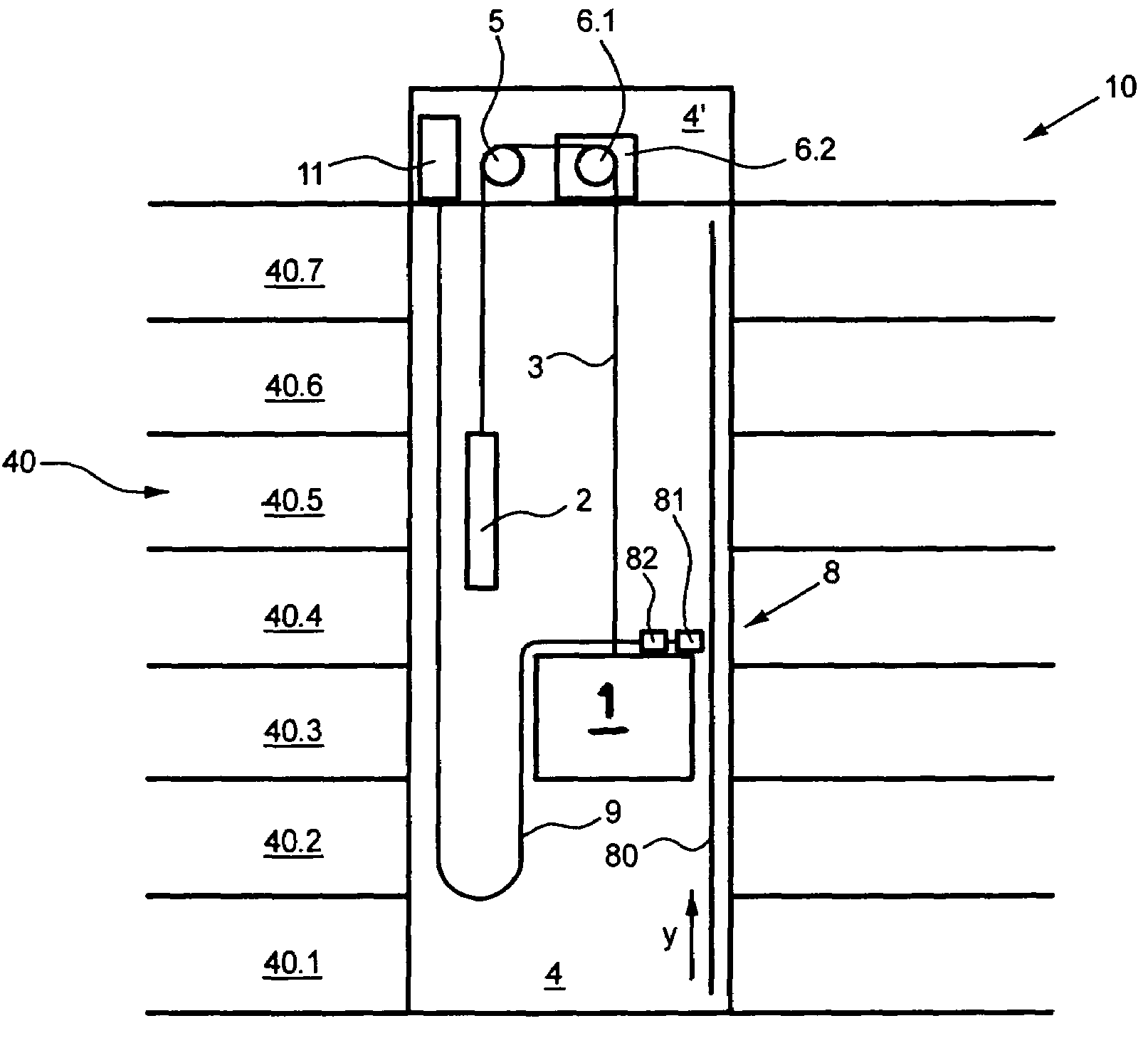
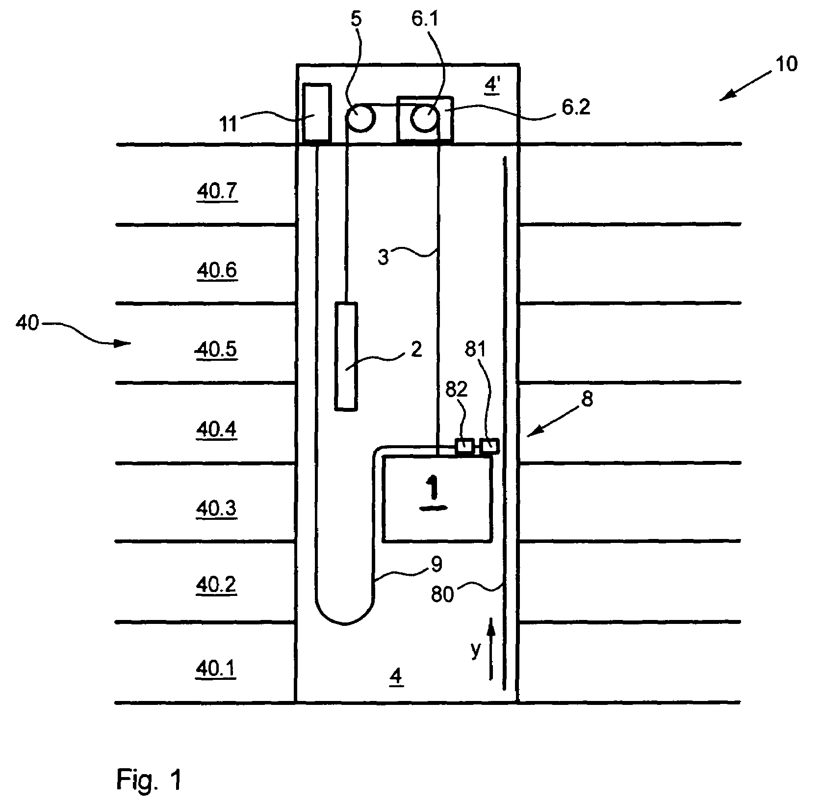
Elevator installation and method for determining and analyzing an elevator car position

a technology for elevators and car positions, applied in the direction of elevators, instruments, transportation and packaging, etc., can solve the problems of increasing reducing the strength of magnetic fields, so as to achieve the effect of ensuring the accuracy of measurement, and reducing the cost of production

Active Publication Date: 2009-07-21
INVENTIO AG
View PDF15 Cites 22 Cited by
  • Summary
  • Abstract
  • Description
  • Claims
  • Application Information

AI Technical Summary

Benefits of technology

[0010]An advantage of the present invention lies in the substantially greater certainty and reliability that, in the normal operating state and in every allowable position of the car, the sensor device delivers to the analyzer and therefore to the elevator control the correct information regarding the current position of the car.
[0011]According to a particularly preferred embodiment of the present invention, the sensor groups are at a suitable distance from each other perpendicular to the direction of their line. This has the effect that, for a given pattern of the signal strength of-the code marks, largest possible lateral offsets between the sensor device and the line of the code marks as well as largest possible distances between the code marks and the sensors are allowable, since the sensor groups detect the magnetic fields of the code marks independent of each other, there being always at least one of the two sensor groups positioned in a favorable area of the code mark signal strength even if the sensor device is relatively greatly offset relative to the line of the code marks in the direction perpendicular to the direction of travel. Furthermore, by this means the width of the code marks measured perpendicular to the direction of travel can be kept relatively small, which has substantial advantages in relation to the limited space for building-in the code mark pattern as well as in relation to the method of its production and the costs of its production.
[0012]It is advantageous for the distance between the two sensor groups to be so chosen that at least the sensors of one of the two sensor groups deliver the complete information regarding the current position of the car, provided that measured perpendicular to the line of the code marks the deviation of the current position of the sensor device from its centered position relative to the line of the code marks does not exceed a value of 25%, preferably 30%, of the width of the code marks.
[0013]It is advantageous for the distance between the two sensor groups to be so chosen that each of the two sensor groups can scan the complete code word corresponding to the current position of the car—i.e. can deliver the complete information regarding the current position of the car—provided that, measured perpendicular to the line of the code marks, the deviation of the position of the sensor device from its optimal position relative to the line of the code marks does not exceed a value of, for example, 10%, preferably 15%, of the width of the code marks.
[0014]According to an expedient embodiment of the present invention, the sensors which are respectively assigned to a sensor group are arranged in two lines of sensors running parallel to the line of the code marks. This embodiment has the advantage that sensors can also be used whose housing dimensions do not permit their arrangement on a single line.
[0015]According to a particularly preferred embodiment of the present invention, the sensors which are respectively assigned to a sensor group are each arranged in a single line parallel to the line of the code marks. By using one single line for the code marks and one single line for the sensors of each sensor group, efficient and loss-free scanning of the code marks takes place in an area in which these display a high signal strength. This takes account of the fact that, not only does a given signal strength of the code marks diminish toward the edges of the code marks but it also diminishes with increasing distance from the surface of the code marks. The efficient and loss-free scanned signal strengths of the code marks, in conjunction with the use of two complete sensor groups spaced from each other perpendicular to the direction of their line, result in a greatest possible range of confidence, i.e. in a large range of the possible position of the sensors relative to the code marks in which the sensors can scan the code marks certainly and reliably with sufficiently strong sensor signals. It is thus possible to devise the range of confidence intentionally, i.e. to optimize mutually dependent allowable ranges of the distance between the code marks and the sensors as well as the lateral offset of the sensor devices relative to the line of the code marks. With the proposed means, the outlay cost for guiding the sensor device relative to the code mark pattern is reduced without the certainty and reliability of the position detection of the car, and therefore of the elevator installation, being impaired.

Problems solved by technology

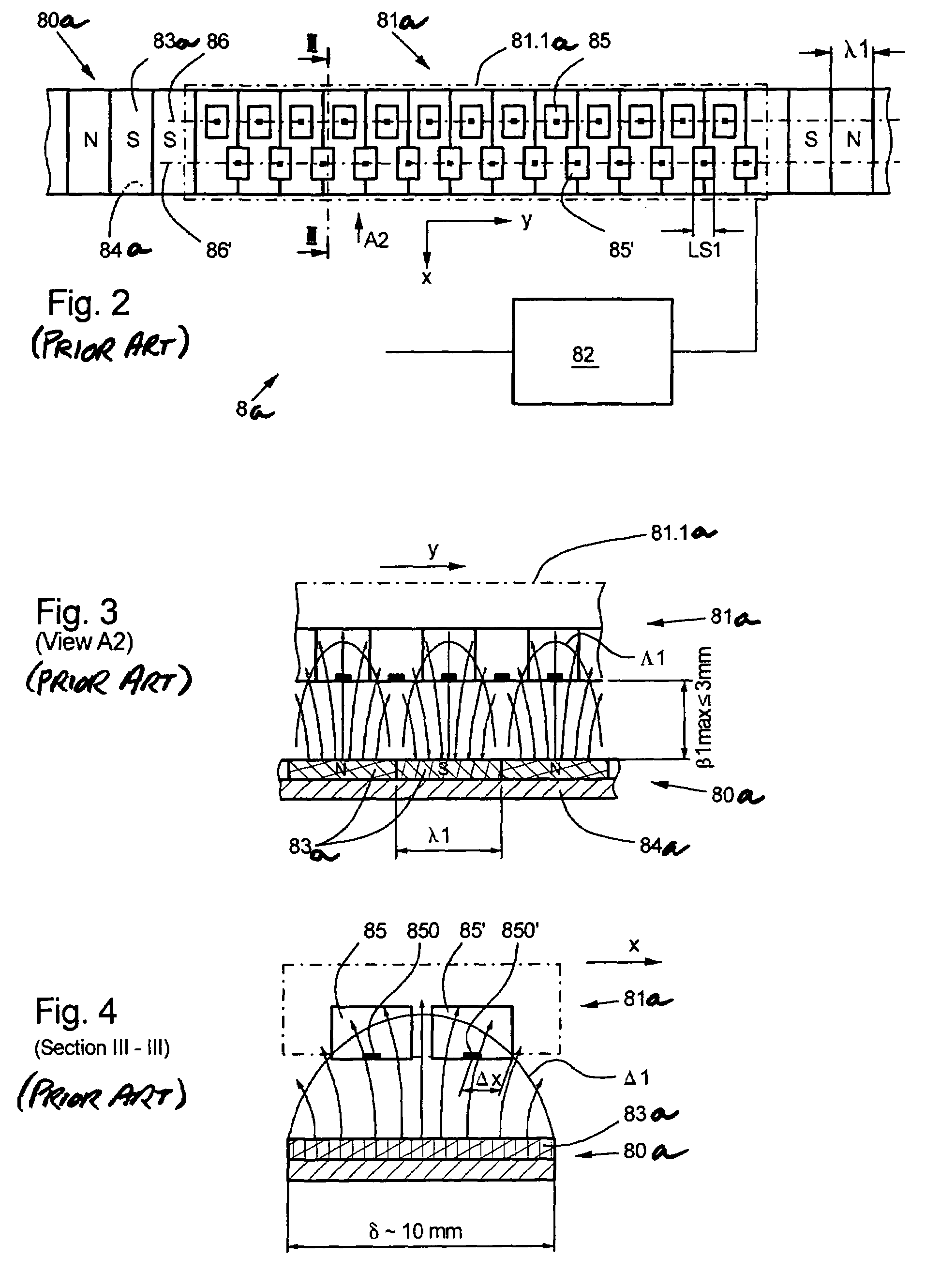
Also disadvantageous in this known device is that the strength of the magnetic field diminishes rapidly in the perpendicular direction above the code marks and the sensors must therefore be positioned at a small distance of 3 mm above the code marks.
Particularly in the case of high car speeds of 10 meters per second the associated outlay is very large.

Method used


Image

  • Elevator installation and method for determining and analyzing an elevator car position
  • Elevator installation and method for determining and analyzing an elevator car position
  • Elevator installation and method for determining and analyzing an elevator car position

Examples


first embodiment

[0043]FIG. 5 shows a device 8a for determining the car position according to the present invention. Shown again are a single-line code mark pattern 80b with code marks 83b of length λ2 which is arranged in the elevator hoistway in a positionally fixed manner, a sensor device 81b with a number of the sensors 85, 85′ which are integrated in a sensor housing 81.1b and scan the code mark pattern 80b, and the analyzer 82. According to the present invention, the sensor device 81b contains two complete sensor groups 87 and 88 which each have two rows of sensors 87.1, 87.1′ and 88.1, 88.1′, each of which encompasses a number of the sensors 85 and 85′ respectively. In each case, along the length of travel the sensors 85′ are arranged offset by half the length λ2 / 2 of the code marks 83b relative to the sensors 85. Each of the two complete sensor groups 87, 88 has essentially the same functions as the sensor group of FIG. 2 described above. Both of the sensor groups 87, 88 scan the code marks ...

second embodiment

[0050]FIG. 8 shows a second embodiment according to the invention of a device 8c for determining the position of the car. Shown again are an elevator hoistway with a single-line code mark pattern 80c arranged in a positionally fixed manner with code marks 83c of length λ3, a sensor device 81c with a number of the sensors 85, 85′ which scan the code mark pattern 80c and are integrated in a sensor housing 81.1c, and the analyzer 82. According to the present invention, this sensor device 81c also contains two complete sensor groups 87, 88. Each of the two sensor groups encompasses sensors 85 and, offset by half of their respective length (λ3 / 2) relative to these in the direction of travel y, sensors 85′, in the present variant embodiment all of the sensors 85 and 85′ which are assigned to one of the sensor groups 87, 88 respectively being arranged in one single sensor line 87.1, 88.1. The latter is possible in this case because the relationship between the length λ3 of the code marks 8...


PUM


Abstract

An elevator installation with at least one car includes at least one device for determining a position of the car and a method of operating such an elevator installation. The position determining device has a code mark pattern and a sensor device. The code mark pattern is arranged along the length of travel of the car and consists of a multiplicity of code marks. The sensor device is mounted on the car and has sensors contactlessly scanning the code marks. The code marks are arranged in a single line and the sensor device comprises at least two sensor groups which are separated from each other perpendicular to the line of the code marks, which makes reading the code marks possible even if there are lateral displacements between the sensor device and the line of the code marks.

Description

BACKGROUND OF THE INVENTION[0001]The present invention relates to an elevator installation with a car and a device for determining a car position and to a method of operating such an elevator installation.[0002]Determining the car position of an elevator installation to derive from this information control signals which are subsequently used by the elevator control is known. Thus, German utility model DE9210996U1 describes a device for determining the car position by means of a magnetic strip and a magnetic head for reading the magnetic strip. The magnetic strip has a magnetic coding and extends along the entire length of travel of the car. The magnetic head which is mounted on the car reads the coding contactlessly. From the coding which is read, a car position is determined.[0003]A further development of this device is disclosed in patent specification WO 03011733A1. According to the description contained in that patent specification, the coding of the magnetic strip consists of a...

Claims


Application Information

Patent Timeline
Patent Type & Authority Patents(United States)
IPC IPC(8): B66B3/02B66B1/34
CPCB66B1/3492
Inventor MARCHESI, ENRICO
Owner INVENTIO AG
Why Eureka
Try Eureka