Electrosurgical device with floating-potential electrodes

a floating-potential electrode, electrosurgical technology, applied in the field of electrosurgical devices with floating-potential electrodes, can solve the problems of shortening the power supply, generating sparks of the probe, and localized melting and vaporization of the electrodes themselves, and achieves a larger, controlled and uniform lesion, and shortens the time required to form steam bubbles and achieve arcing within the bubbles

Inactive Publication Date: 2009-07-21
ELECTROMEDICAL ASSOCS
View PDF3 Cites 22 Cited by
  • Summary
  • Abstract
  • Description
  • Claims
  • Application Information

AI Technical Summary

Benefits of technology

[0021]Power density in close proximity of the tip depends primarily on the applied voltage, the shape and size of the exposed portion of the electrode, and liquid / tissue electrical conductivity. Also it is affected by the return current electrode size, shape, and position. In general, positioning the return electrode into closer proximity to the active electrode increases the power density in the region near the electrode tip.
[0039]The current invention is useful also for medical procedures in which tissue is thermally treated rather than removed by vaporization, such as, for instance, cardiology, oncology and treatment of tumors, sometimes referred to as lesion formation. In these applications the device is brought into close proximity, or contact, with tissue with or without the presence of externally applied conductive fluid at the site for thermal treatment. The voltage applied to the active electrode is reduced to a level which produces current densities insufficient for forming sparks and the associated bubbles. Tissue is heated to a desired temperature for a predetermined time sufficient for lesion formation. The floating electrode intensifies the electric field in the region surrounding the active electrode so as to produce a larger, more controlled and more uniform lesion.

Problems solved by technology

A problem arises when the probe is generating sparks.
Usually this leads to extra high-energy deposition in the spark between metallic electrodes resulting in localized melting and vaporization of the electrodes themselves.
This results in shorting of the power supply and destruction of both the active and return electrodes with little clinical benefit to the patient.

Method used


Image

  • Electrosurgical device with floating-potential electrodes
  • Electrosurgical device with floating-potential electrodes
  • Electrosurgical device with floating-potential electrodes

Examples


Embodiment Construction

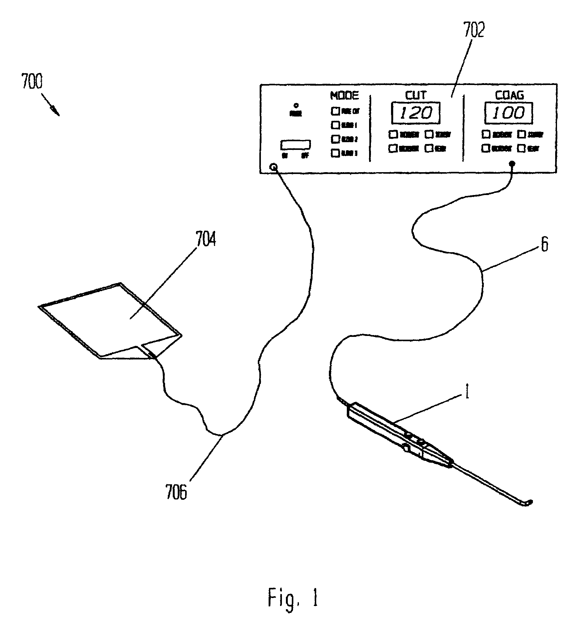
[0122]Referring to FIG. 1, electrosurgical system 700 has an electrosurgical power supply 702, an electrosurgical probe 1 with electrical cord 6, and a dispersive (return) electrode 704 with electrical cord 706.

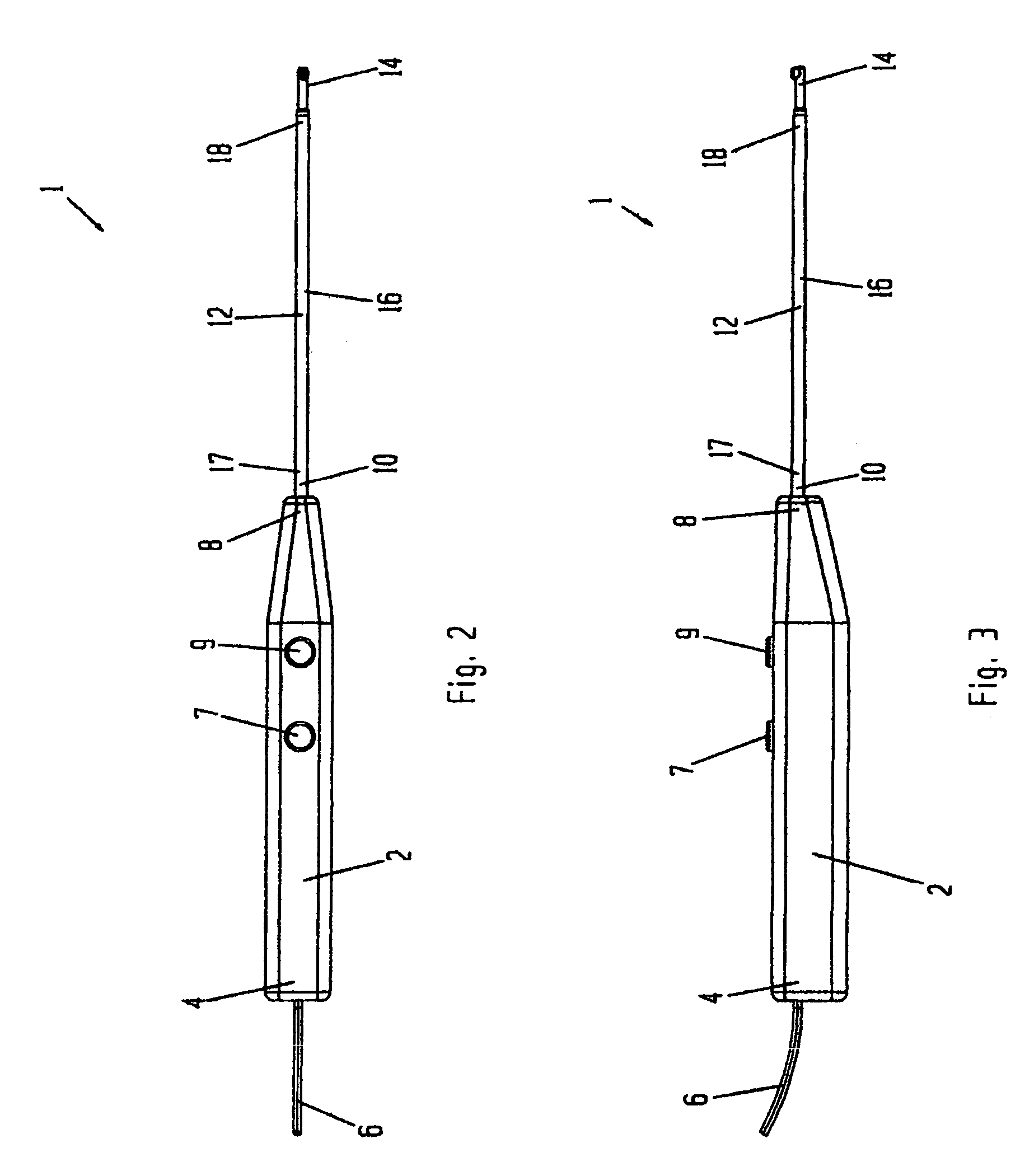
[0123]Referring FIGS. 2 through 4, probe 1 has a proximal portion 2 forming a handle and having a proximal end 4 from which passes electrical cord 6, and a distal end 8 which attaches to proximal end 10 of elongated distal portion 12. Distal portion 12 has a distal end 14 and a tubular portion 16. Tubular portion 16 has a proximal end 17 and a distal end 18. Buttons 7 and 9 control the RF power applied to the probe.

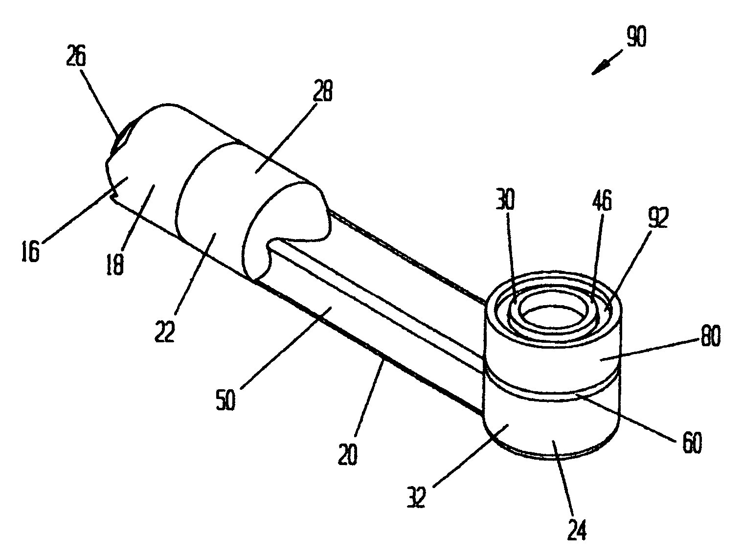
[0124]Distal end 14 is an assembly having an active electrode, a ring electrode, a ceramic or other dielectric insulator placed between the active and ring electrodes, and a dielectric coating which covers at least a portion of the distal end assembly. The distal end assembly and its components are shown in FIGS. 5 through 17.

[0125]Referring to FIGS. 5 through 7, a...


PUM


Abstract

An electrosurgical instrument, system and methods are provided for the vaporization, cutting, coagulation, or treatment of tissue in the presence of an electrically conductive fluid medium. The electrosurgical probe comprises at least one active electrode, and at least one “floating” electrode having at least one end in close proximity to at least one active electrode. The floating electrode is not connected in any way to the electrosurgical power supply, but rather has a “floating” potential determined by the shape and position of the electrode. The floating electrode increases current density in the region of the probe distal end.

Description

PRIORITY[0001]This application claims the benefit of provisional application 60 / 493,729 filed Aug. 11, 2003.BACKGROUND OF THE INVENTION[0002]The present invention relates generally to the field of electrosurgery, and, more particularly, to high efficiency surgical devices and methods which use high frequency (RF) electrical power for cutting, bulk removal by vaporization (ablation), coagulation and treatment of tissue in a conductive liquid environment, as well as other forms of tissue treatment such as shrinking, lesion formation, sculpting and thermal treatment with or without externally supplied liquids.[0003]Least invasive surgical techniques have gained significant popularity because of their ability to accomplish outcomes with reduced patient pain and accelerated return of the patient to normal activities. Arthroscopic surgery, in which the intra-articular space is filled with conducting fluid, allows orthopedists to efficiently perform procedures using special purpose instrum...

Claims


Application Information

Patent Timeline
Patent Type & Authority Patents(United States)
IPC IPC(8): A61B18/18A61B18/14
CPCA61B18/148
Inventor CARMEL, YUVALSHKVARUNETS, ANATOLYVAN WYK, ROBERT A
Owner ELECTROMEDICAL ASSOCS
Why Eureka
Try Eureka