Measuring system

a measuring system and measuring system technology, applied in the field of measuring systems, can solve the problems of high cost of surveying operation, low working efficiency, and difficulty in having an assistant surveyor with sufficient surveying knowledge and surveying technique, so as to improve the efficiency of surveying operation, facilitate the collection of data, and facilitate the effect of surveying operation smooth and efficient

Active Publication Date: 2009-07-21
KK TOPCON
View PDF15 Cites 58 Cited by
  • Summary
  • Abstract
  • Description
  • Claims
  • Application Information

AI Technical Summary

Benefits of technology

[0006]It is an object of the present invention to provide a measuring system, by which it is possible to acquire surveying data in simpler and easier manner without requiring sufficient knowledge and technique of surveying operation and to improve the working efficiency and to reduce the surveying cost.

Problems solved by technology

This means that the operation is carried out on one person to one person basis, and the working efficiency is low.
The assistant surveyor must have certain knowledge on surveying operation and surveying techniques, and this leads to such a problem as higher cost for the surveying operation.
At an operation site of a small-scale construction project, for instance, it is often difficult to have an assistant surveyor with sufficient surveying knowledge and surveying technique, and a single surveyor must sometimes execute at the same time the duties of a skilled surveyer, the duties of an engineer at the working site and the duties as a superintendent at the construction site.
As a result, the operation requires complicated procedure and is not very efficient.

Method used


Image

  • Measuring system
  • Measuring system
  • Measuring system

Examples


Embodiment Construction

[0034]Description will be given below on the best mode when the present invention is carried out by referring to the attached drawings.

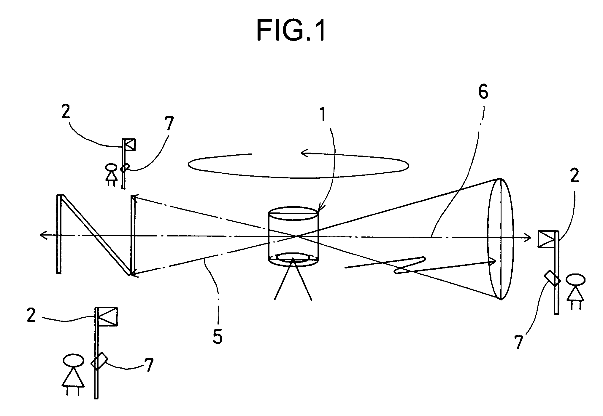
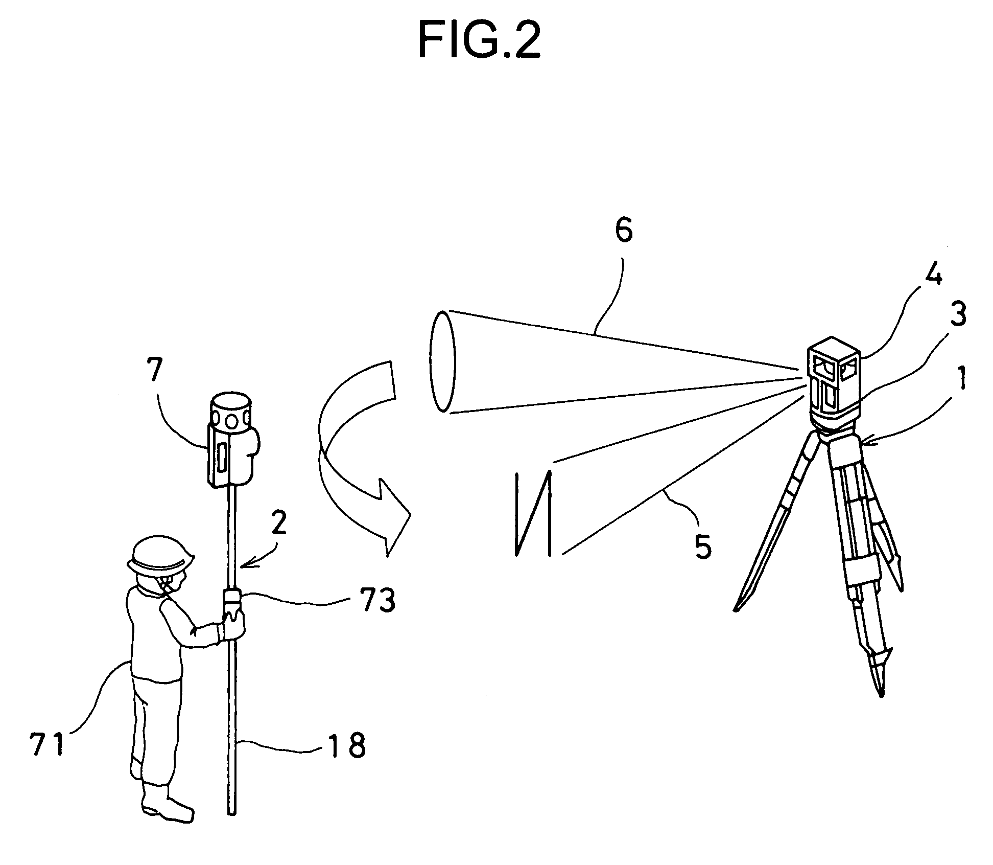
[0035]First, referring FIG. 1 and FIG. 2, description will be given on general features of a measuring system in an embodiment of the invention.

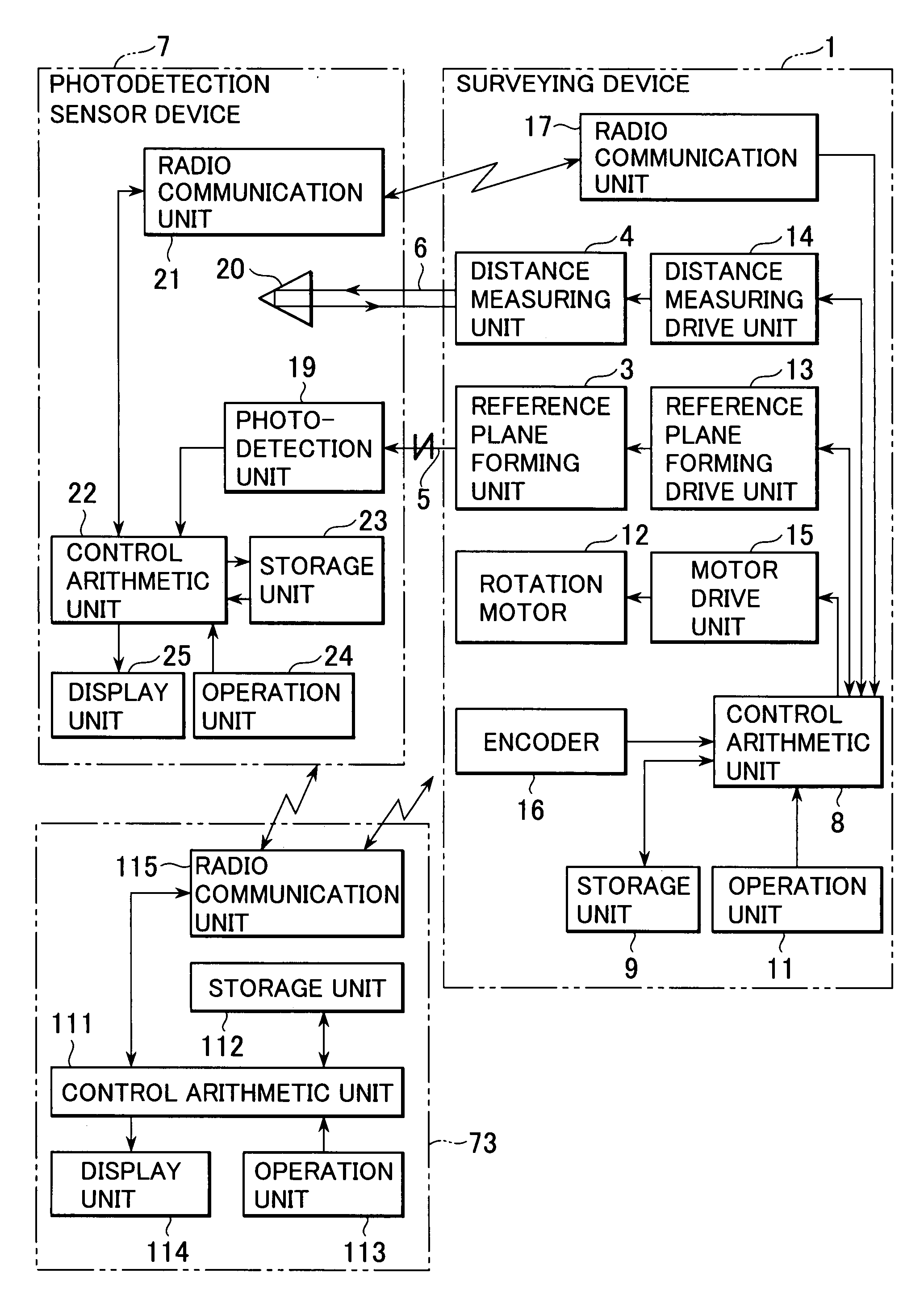
[0036]In a surveying device 1 shown in FIG. 1, a horizontal reference plane can be formed and a distance to an object to be measured 2 can be determined.

[0037]The surveying device 1 comprises a reference plane forming unit 3 and a distance measuring unit 4. The surveying device 1 is installed at a known point. A laser beam 5 for forming a reference plane is projected at a constant velocity by rotary irradiation, and a distance measuring light 6 can be projected by rotary irradiation. By receiving the distance measuring light 6 reflected from the object to be measured 2, distances to two or more objects to be measured 2 can be determined.

[0038]The reference plane forming unit 3 projects a laser beam 5 for form...


PUM


Abstract

The present invention provides a measuring system, which comprises a surveying device installed at a known point, at least one photodetection device to be installed at a measuring point, and a main arithmetic device; wherein the surveying device projects by rotary irradiation a reference plane forming laser beam including two or more fan-shaped laser beams with at least one of the fan-shaped laser beams tilted and a distance measuring light performs distance measurement by receiving a reflected distance measuring light, and performs communication of the distance measurement data between the photodetection device and the main arithmetic device; wherein the photodetection device calculates an elevation angle with respect to the surveying device based on a photodetection signal issued by receiving the reference plane forming laser beam, calculates an elevation position based on the elevation angle and the distance to the surveying device, and performs communication of distance measurement data and elevation position data at least with the main arithmetic device; and wherein the main arithmetic device communicates at least with the photodetection device among the surveying device and the photodetection device, and collects and records surveying data such as distance measurement data, elevation position data, etc. for each measuring point.

Description

BACKGROUND OF THE INVENTION[0001]The present invention relates to a measuring system to be used when surveying operation is performed by one operator or through cooperative activities of two or more surveying operators.[0002]In the surveying operation, which is carried out in civil engineering projects, e.g. in road construction work, such operations are carried out as measurement of positions on both sides of road, measurement of elevation (high-low) difference, measurement of road width, etc. In this sense, surveying operation is cooperative work by a plurality of surveying operators.[0003]In the past, when surveying operation is performed by using a total station, piles are driven at a predetermined distance (e.g. 10 m or 20 m) along both sides of road. An assistant surveyor holds an object to be measured (e.g. a pole with a prism mounted on the pole) at a point where a pile is to be driven. A skilled surveyor (a chief surveyor) performs surveying operation on the object to be me...

Claims


Application Information

Patent Timeline
Patent Type & Authority Patents(United States)
IPC IPC(8): G01C3/08G01C1/00
CPCG01C3/08G01C15/002G01S7/003G01S17/42G01S7/497G01S7/4817G01S17/36
Inventor SAKIMURA, RITSUOSINOZAKI, HAJIME
Owner KK TOPCON
Why Eureka
Try Eureka