Acoustic device

a bending wave and acoustic device technology, applied in the direction of diaphragm construction, electromechanical transducer, transducer diaphragm, etc., can solve the problems of sound power waste, degrade performance, degrade sound, etc., to reduce intelligibility, reduce the directivity of wide horizontal plane bending wave, and minimise mounting difficulties

Active Publication Date: 2009-07-21
GOOGLE LLC
View PDF7 Cites 17 Cited by
  • Summary
  • Abstract
  • Description
  • Claims
  • Application Information

AI Technical Summary

Benefits of technology

[0018]The coincidence frequency of the panel is preferably approximately equal to or greater than the highest desired frequency. Otherwise, the vibration exciting means acting as the restraining means may produce strong off-axis lobing at the coincidence frequency which in turn may disrupt the reverberent sound-field in the acoustic space and reduce intelligibility.
[0019]In contrast to the teaching of WO00 / 78090, modes are encouraged for the minor cross axis to provide wide horizontal plane bending wave directivity when the rectangular panel is vertically orientated, as is common with public address speakers. Such an orientation also minimises mounting difficulties for architects and contractors. The speaker of the present invention may thus be considered to have the opposite acoustic effect of the speaker of WO00 / 78090. It is opposite both in principle and in action.

Problems solved by technology

If this narrower directivity requirement for the sound radiation in the vertical plane is not satisfactorily provided, sound power is wasted in driving the overall volume presented by the concourse and this wasted sound also degrades performance by echoing or reverberating around the space, degrading signal to noise ratio and reducing intelligibility.
Conventional piston / cone type line source speakers can achieve this to some degree, but suffer from significant interference between the arrays of piston elements at higher frequencies, which do not sum well in the acoustic space.
If the piston elements are then made smaller to address this issue, they have poorer low frequency output and power handling.
If they are too large, the interference effects become dominant, spoiling the directivity performance.
Compromises are therefore inevitable when using conventional piston drivers.

Method used


Image

  • Acoustic device
  • Acoustic device
  • Acoustic device

Examples


Embodiment Construction

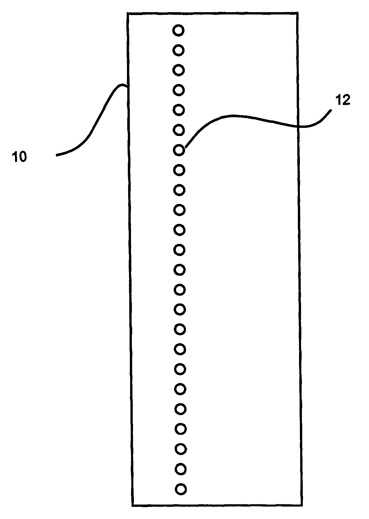
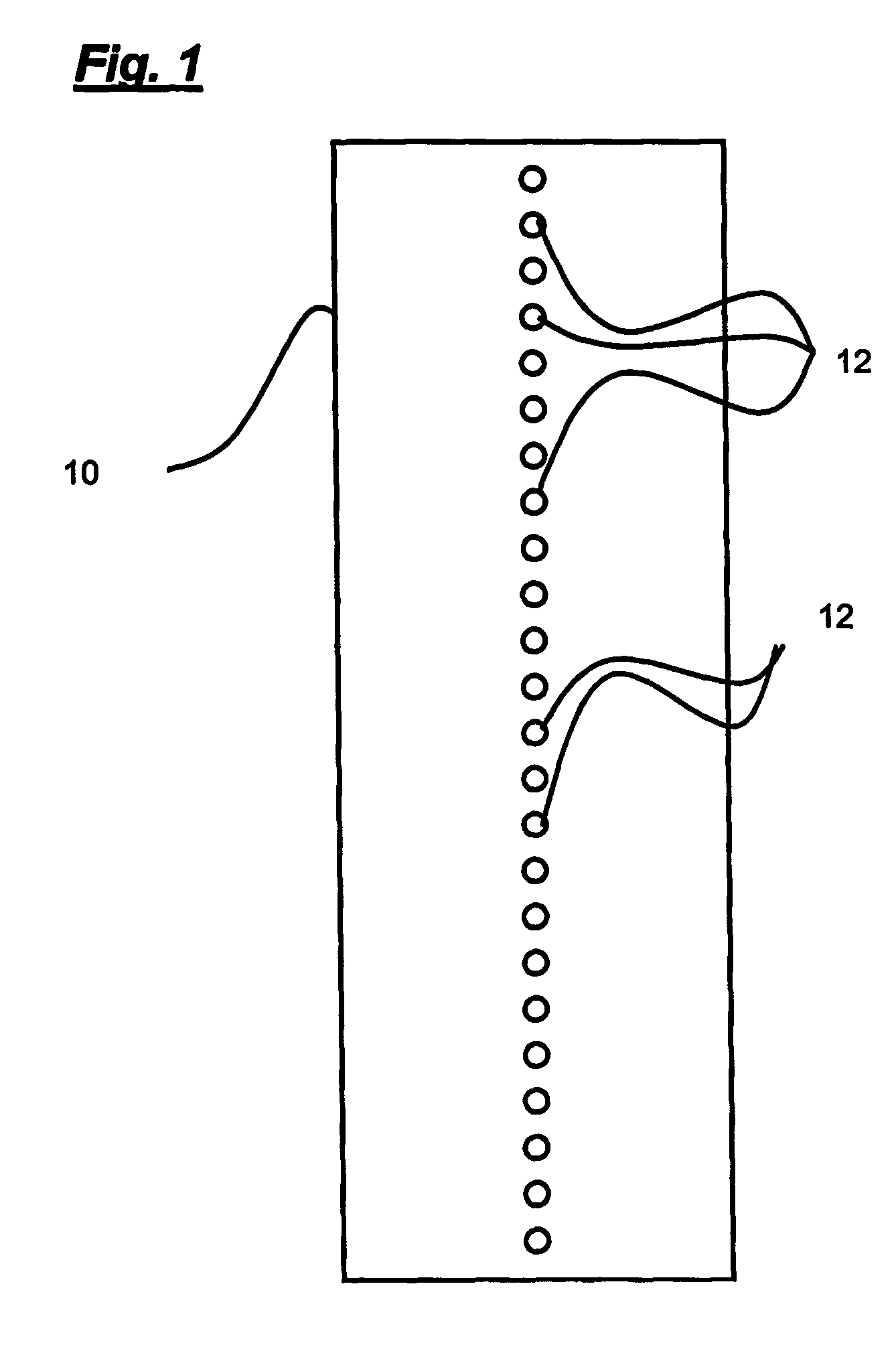
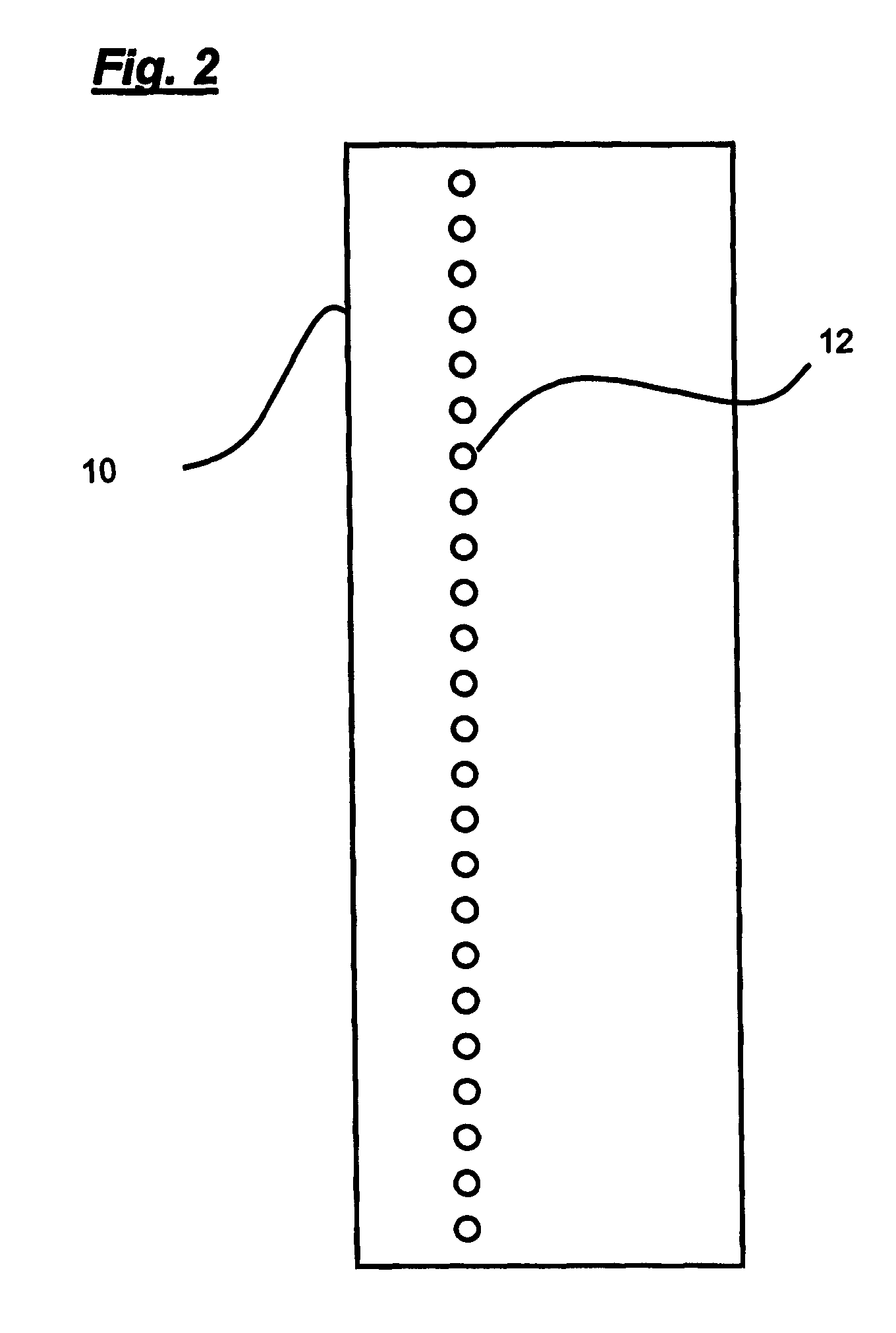
[0028]FIGS. 1 and 2 show a loudspeaker comprising a panel 10 to which an array of twenty-four exciters 12 are mounted to drive bending wave vibration in the panel. The panel is large having dimensions of 120 cm by 40 cm and thus has an aspect ratio of 3:1. Each exciter has a diameter of 25 mm and the array of exciters extends from one short end to the other short end of the panel.

[0029]In FIG. 1 the exciters 12 are equally spaced in a line running along the length of the long axis of the panel 10. In FIG. 2 the exciters 12 are equally spaced on an off-axis line running along the length of the panel 10. The off-axis line is the nodal line of the first lateral bending wave mode.

[0030]FIG. 3 shows the simulated frequency responses 20, 22 for the loudspeakers of FIGS. l and 2 as solid and dashed lines respectively. The acoustic response of the loudspeaker of FIG. 1 has a significant drop in sound pressure level at the first resonant bending wave mode of the panel, namely at 100 Hz. By m...


PUM


Abstract

A bending wave loudspeaker having an operating frequency range and a coincidence frequency which is above the operating frequency range, comprising a resonant panel having two generally orthogonal axes, vibration exciting means coupled to the panel to excite the panel into resonance along the one axis of the panel, and means restraining or preventing resonance along the other axis of the panel whereby the panel radiates an acoustic output which is of wide directivity along the one axis and of narrow directivity along the other axis of the panel.

Description

[0001]This application claims the benefit of U.S. provisional application No. 60 / 489,907, filed July 25, 2003.TECHNICAL FIELD[0002]This invention relates to acoustic devices and more particularly to bending wave acoustic devices, e.g. loudspeakers.BACKGROUND ART[0003]Bending wave panel speakers, particularly Distributed Mode panel speakers, otherwise known by the achronym “DML”, such as taught in WO 97 / 09842 and others to the present applicant, have the property of diffuse sound radiation resulting from complex bending wave action which beneficially provides wide directivity in all planes or directions. However in some applications a narrower directivity may be important, particularly in some axes or planes relative to others.[0004]For public address purposes, for example for an airport concourse, the output of a loudspeaker is intended to be directed at the subjects. Maximum intelligible sound power is ideally directed over a specified range of height and over a wide horizontal are...

Claims


Application Information

Patent Timeline
Patent Type & Authority Patents(United States)
IPC IPC(8): H04R25/00H04R11/02H04R7/04
CPCH04R7/045H04R1/32
Inventor BANK, GRAHAMMARCHANT, ANDREWCOLLOMS, MARTINBURTON, PAUL
Owner GOOGLE LLC
Why Eureka
Try Eureka