
Radio base system, transmission directional control method, and transmission directional control program

a transmission directional control and radio base station technology, applied in multiplex communication, wireless communication, polarisation/directional diversity, etc., can solve the problem of deterioration of transmission directivity from the base station, large deviation of extrapolation results from the actual time waveform of the reception response vector, and error between

Inactive Publication Date: 2009-07-21
SANYO ELECTRIC CO LTD +1
View PDF3 Cites 7 Cited by
  • Summary
  • Abstract
  • Description
  • Claims
  • Application Information

AI Technical Summary

Benefits of technology

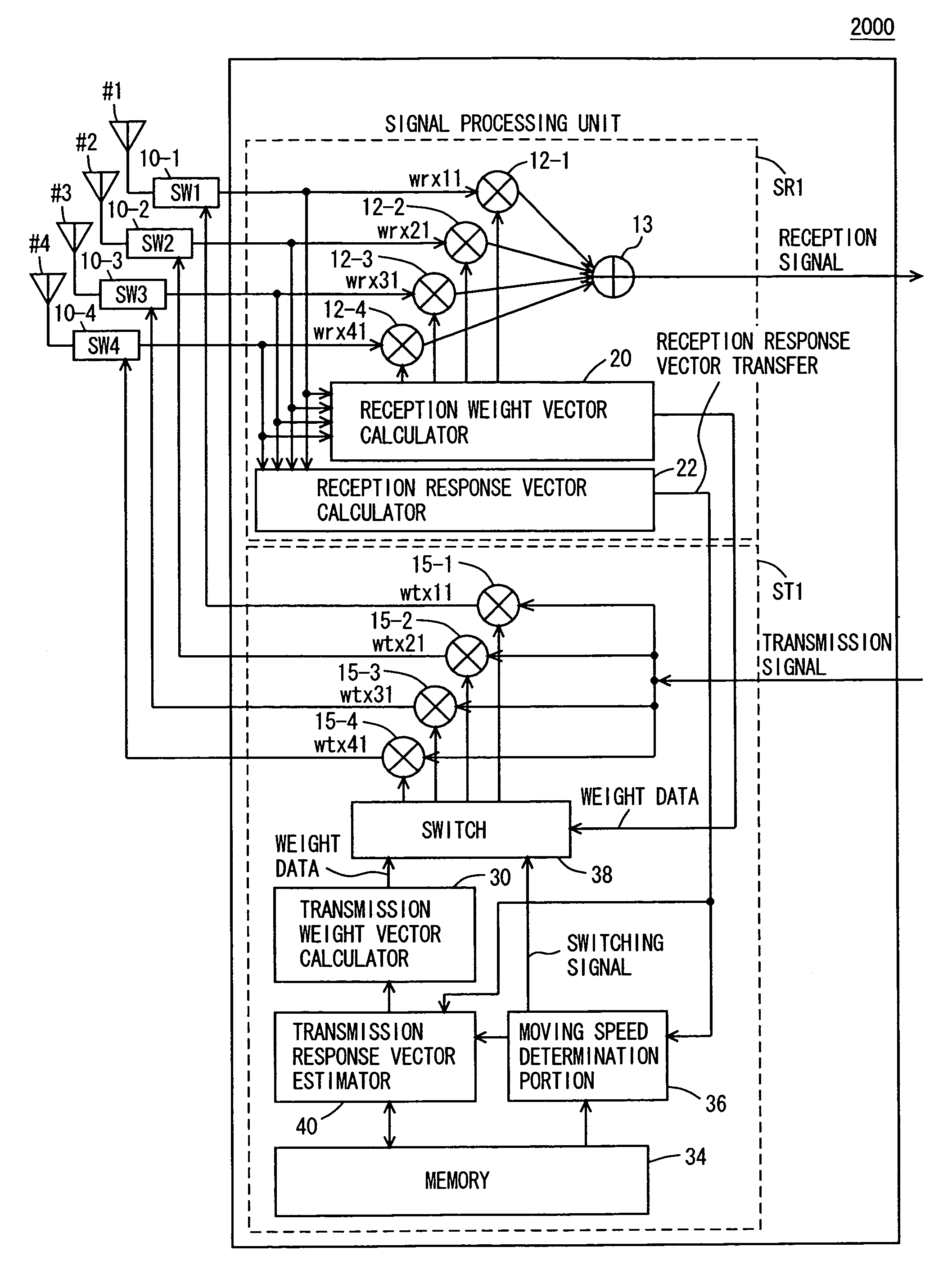
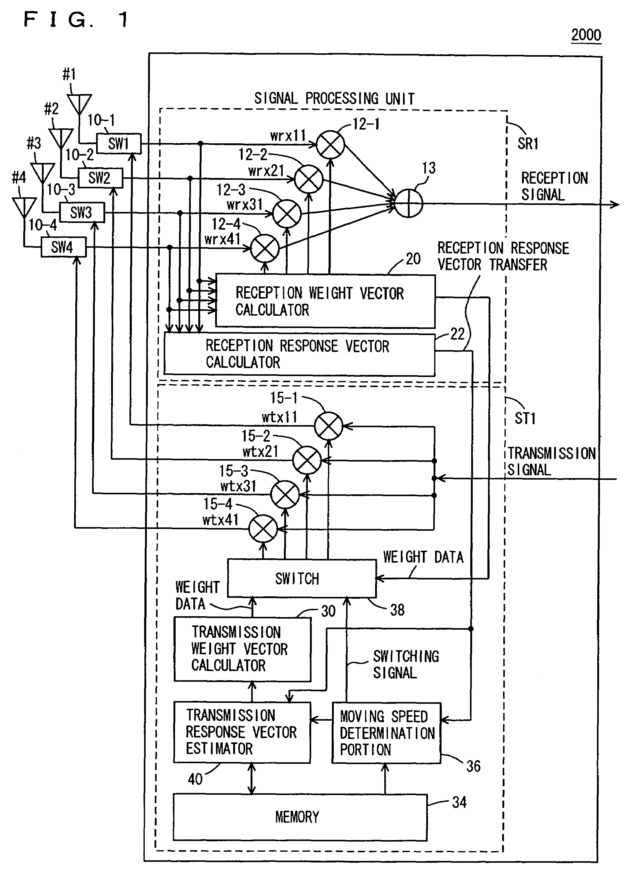
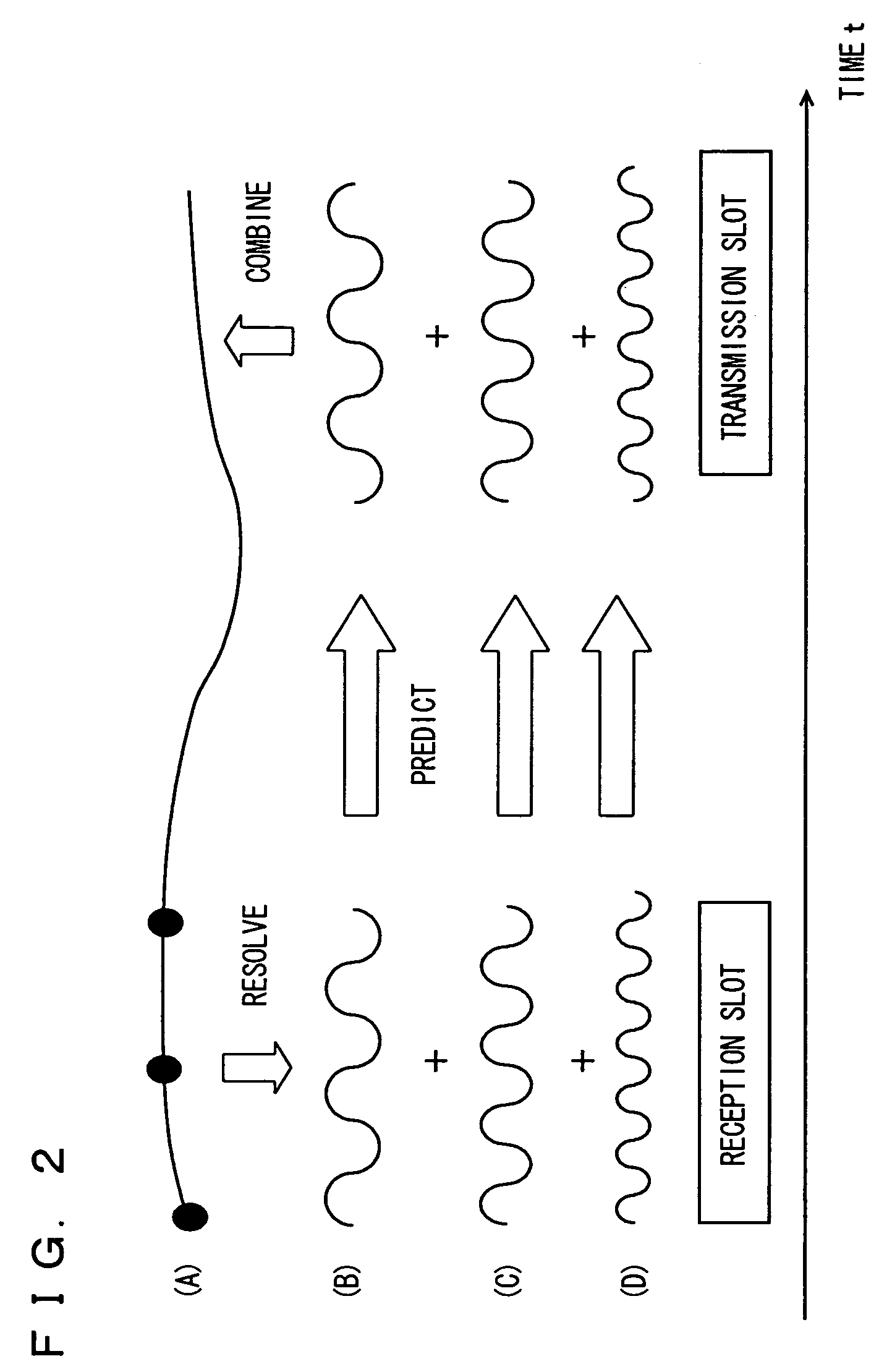
[0042]As described above, according to the present invention, attention is paid to the fact that temporal change of the reception response vector due to change in the propagation environment is represented as a composite of signal waveforms of a plurality of frequencies. Change in transmission for each of a prescribed number of prescribed frequency components which are different from each other is predicted and combined, whereby the reception response vector at that time is estimated and used for controlling transmission directivity in the radio base station system. Therefore, compared to an example in which the reception response vector in transmission is estimated with the extrapolation processing, more accurate control of transmission directivity can be achieved. In particular, even if the terminal moves with a high speed, and the Doppler frequency is high, spatial multiple access of a plurality of terminals to the radio base station system can be maintained.

Problems solved by technology

When the reception weight vector obtained in the uplink is used as it is in the downlink as the transmission weight vector as described above, and if a moving speed of the terminal is not negligible, there will be an error between a direction of emission of the radio wave from the base station and a direction in which the terminal is actually present.
This will lead to deterioration of transmission directivity from the base station in the downlink.
With the method using the extrapolation processing as described above, however, if the moving speed of the terminal is increased, and the time waveform of the reception response vector abruptly fluctuates with a cycle being short, an extrapolation result will considerably deviate from an actual time waveform of the reception response vector, and an extrapolation error will be large.
In particular, if the Doppler frequency representing the moving speed of the terminal exceeds FD=40 Hz, spatial multiple access can no longer be maintained.

Method used


Image

  • Radio base system, transmission directional control method, and transmission directional control program
  • Radio base system, transmission directional control method, and transmission directional control program
  • Radio base system, transmission directional control method, and transmission directional control program

Examples


Embodiment Construction

[0050]In the following, embodiments of the present invention will be described in detail with reference to the figures. It is noted that the same reference characters refer to the same or corresponding components in the figures, and description therefor will not be repeated.

[0051]Before describing the embodiment of the present invention, estimation of a transmission response vector using a conventional extrapolation processing, as well as control of transmission directivity in the base station will initially be described.

[0052]FIG. 5 is a functional block diagram for functionally illustrating a configuration of a base station 1000 for estimating a transmission response vector with the conventional extrapolation processing performed with software by a digital signal processor (DSP).

[0053]In the configuration shown in FIG. 5, in order to identify two users PS1 and PS2, four antennas #1 to #4 are provided. Here, more generally, N antennas (N: natural number) may be provided.

[0054]In ba...


PUM


Abstract

A radio unit (2000) separates a signal from a specific terminal among signals from array antennas (#1-#4) based on a reception weight vector calculated by a reception weight vector calculator (20). A reception response vector calculator (22) derives a reception response vector of a propagation path for the signal from the specific terminal. A transmission response vector estimator (40) regards an estimation result of the reception response vector calculator (22) as a composite waveform of a function of a plurality of frequencies, determined in accordance with a Doppler frequency, and predicts a transmission response vector at a time point of transmission by obtaining coefficients of respective function. A transmission weight vector calculator (30) controls antenna directivity in transmission, based on a prediction result of the transmission response vector estimator (40).

Description

TECHNICAL FIELD[0001]The present invention relates to a radio base station system as well as a method and a program for controlling transmission directivity, and more particularly to a radio base station system in which directivity of an array antenna is modified in real time so that signals are transmitted / received to / from a plurality of mobile terminals in a mobile communication system, as well as a method and a program for controlling transmission directivity in such a radio base station system.BACKGROUND ART[0002]Recently, in a rapidly-developing mobile communication system (for example, Personal Handyphone System: hereinafter, referred to as “PHS”), in communication between a radio base station system (a base station) and a mobile terminal (a terminal), a scheme for separating and extracting a reception signal from a specific terminal with an adaptive array processing on a side of a base station, among a plurality of terminals that have established spatial multiple access to th...

Claims


Application Information

Patent Timeline
IPC IPC(8): H04M1/00H04B1/38H01Q3/26H04B7/00H04B7/06H04B7/08H04B7/10H04B7/26H04J3/00H04J99/00H04W16/28
CPCH04B7/0452H04B7/086H04B7/0615
Inventor DOI, YOSHIHARUOGAWA, YASUTAKAOHGANE, TAKEO
Owner SANYO ELECTRIC CO LTD
Learn More