Biological optical measurement system

a biological optical measurement and optical measurement technology, applied in the field of optical measurement technology, can solve the problems of difficult to reduce the noise signal of mayer wave using bandpass filter or bandcut filter, and difficult to reduce the noise signal of mayer wave using a simple frequency filter, so as to achieve the effect of reducing the amount of biological noise signal contained in the biological optical measurement signal

Inactive Publication Date: 2009-07-21
HITACHI LTD
View PDF20 Cites 3 Cited by
  • Summary
  • Abstract
  • Description
  • Claims
  • Application Information

AI Technical Summary

Benefits of technology

[0023]In accordance with the invention, the amount of biological noise signal contained in a biological optical measurement signal can be reduced.

Problems solved by technology

Therefore, because the frequency band of the Mayer wave noise signal is very close to the frequency bands of brain activity signals, it is difficult to reduce the Mayer wave noise signal using bandpass filters or bandcut filters.
In addition, because the low-frequency fluctuation signal contains irregular and non-periodic changes, it is difficult to reduce them using a simple frequency filter.

Method used


Image

  • Biological optical measurement system
  • Biological optical measurement system
  • Biological optical measurement system

Examples


embodiment 1

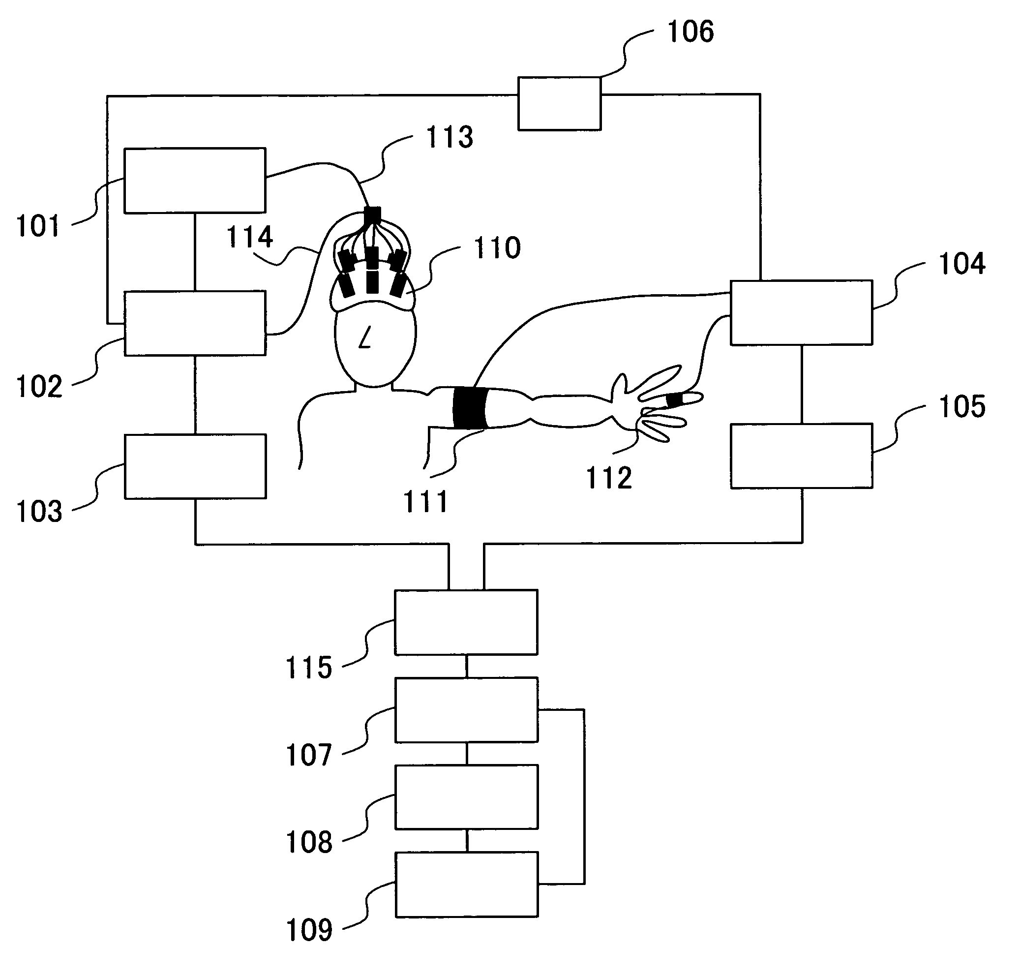
[0033]FIG. 1 shows a diagram of a system according to a first embodiment of the invention.

[0034]In the first step of a procedure, the operator attaches a biological optical measuring probe 110 to a part or the entirety of the head of a subject. The tissue is then irradiated with light produced by a light irradiating unit 101 via optical fibers 113 connected to the biological optical measuring probe 110. The light that has passed through the tissue is then detected by an optical detection unit 102 via an optical fiber 114 connected to the biological optical measuring probe 110. The resultant signal is recorded in a memory unit 103.

[0035]The aforementioned signal recorded in the memory unit 103 is hereafter referred to as “an optical signal.” A blood-pressure measuring cuff 111 for the arm and a blood-pressure measuring cuff 112 for the finger are attached to the arm and a finger, respectively, of the subject. The cuffs, either one of which may be dispensed with, are controlled by a h...

embodiment 2

[0046]FIG. 5 shows a second embodiment of the invention, in which, instead of the blood pressure measuring cuff 111 for the arm and the blood pressure measuring cuff 112 for the finger in the first embodiment, probes 511 and 512 for the measurement of pulsation using light are employed. The device for measuring pulsation using light is known as a pulse oximeter, the measurement principle of which is the same as that of the present embodiment. The probes for pulsation measurement using light consist of one (511) that is disposed near the head, where optical measurement takes place, such as at the ear or the forehead, and / or the other (512) that is attached to a portion of the subject that is spaced apart from the probe 511 by a certain distance, such as the arm. Signals obtained by the pulsation measurement unit 504 are processed by units including the memory unit 505 and the relationship computing unit 507, as in the first embodiment.

embodiment 3

[0047]FIG. 6 shows a third embodiment of the invention, which includes a measurement unit that is identical to the one in Embodiment 5. A blood-pressure computing unit 613 determines the blood pressure from two signals obtained by a pulsation measurement unit 604 based on the pulsation transfer time (Patent Document 4). Alternatively, the pulsation component may be extracted from an optical signal obtained by an optical detection unit 602 and then used in the blood pressure computation unit 613.


PUM


Abstract

A typical task assigned for measuring a brain activity signal lasts from 10 to 30 seconds. The frequency band of the Mayer wave noise signal is very close to the frequency bands of brain activity signals, a result, it is difficult to reduce the Mayer wave noise signal using a bandpass filter or a bandcut filter. Light irradiating units and light detecting units for detecting the emitted light that has been passed through or reflected within the tissue are provided. A biological signal measuring unit measures at least one of the pulsation, breathing, blood pressure, and temperature. The relationship between an optical signal obtained by the light detecting unit and a biological signal using non-linear analysis; and a computation for separating the biological noise signal from the optical signal on the basis of the obtained relationship.

Description

CLAIM OF PRIORITY[0001]The present application claims priority from Japanese application JP 2004-306319 filed on Oct. 21, 2004, the content of which is hereby incorporated by reference into this application.BACKGROUND OF THE INVENTION[0002]1. Field of the Invention[0003]The present invention relates to an optical measurement technology and particularly to an optical measurement method and apparatus for acquiring biological information based on optical signals received from a tissue.[0004]2. Background Art[0005]Measurement signals (to be hereafter referred to as an optical signal) obtained by optically acquiring internal information about a living tissue (such as in JP Patent Publication (JP Patent Publication (Kokai) No. 9-135825 A (1997)) contain noise signals due to several factors, in addition to the target response signal. To reduce the influence of such noise signals, averaging or other techniques using a bandpass filter, for example, are used.[0006]The averaging method for red...

Claims


Application Information

Patent Timeline
Patent Type & Authority Patents(United States)
IPC IPC(8): A61B5/00
CPCA61B5/0059A61B5/6814A61B5/14553A61B5/024
Inventor KATURA, TAKUSIGETANAKA, NAOKISATO, HIROKIOBATA, AKIKOMAKI, ATSUSHI
Owner HITACHI LTD
Why Eureka
Try Eureka