Surface wave transmission system over a single conductor having E-fields terminating along the conductor

a transmission system and conductor technology, applied in waveguides, antenna details, antennas, etc., can solve the problems of insufficient surface layer to shrink the radial extent, general restrictions on the use of insulation or special conditioning of the conductor, and inability to reduce the theory to practice or how to actually launch a surface wave onto the conductor. , to achieve the effect of reducing individual energy consumption, enabling economic incentives, and reducing energy costs

Active Publication Date: 2009-07-28
CORRIDOR SYST INC
View PDF11 Cites 690 Cited by
  • Summary
  • Abstract
  • Description
  • Claims
  • Application Information

AI Technical Summary

Benefits of technology

[0028]Though by no means limited to this use, this invention has particular application to the transport and distribution of high speed information over a three decade frequency range, including most importantly the range of approximately 50 MHZ to 20 GHz, and most importantly including the 50 MHZ to 5 GHz sub-range. The system employs power transmission lines in the existing worldwide power distribution grid as conductors for surface wave transmissions. In addition to providing information transport and mobile communications access, this invention has particular use as a means for reducing energy costs by providing real time control and monitoring information of end-use energy demands. This kind of real time access is an enabling aspect of “Smart Grid” energy utility systems and can enable economic incentive for end users to reduce their individual energy consumption at times of peak energy demand. There have been estimates of several hundred billion dollars of potential savings in the United States alone achievable through the off-loading of only a few percent of current peak energy usage because doing so removes or reduces the necessity of expanding costly energy generation, transmission and distribution systems.

Problems solved by technology

None of these theoretical treatments showed how to reduce the theory to practice or how to actually launch a surface wave onto a conductor.
For frequencies below about 5000 megacycles per second this minute surface layer is insufficient to shrink the radial extent of the field enough to permit the use of a bare conductor with a horn of convenient dimensions.
There were several applications of G-Line, but the need for insulation or special conditioning of the conductor generally restricted its use to off-beat problems; transmission to a device being towed from an airplane, communications within a mine and other situations where the expense of installing a specially prepared line was merited.
This work indicated that without dielectric the wave extends “impractically far” beyond the conductor.
None of this previous work has recognized a way to separate wave transmission along a single unconditioned conductor from simultaneously causing radiation from this same conductor.

Method used


Image

  • Surface wave transmission system over a single conductor having E-fields terminating along the conductor
  • Surface wave transmission system over a single conductor having E-fields terminating along the conductor
  • Surface wave transmission system over a single conductor having E-fields terminating along the conductor

Examples


Embodiment Construction

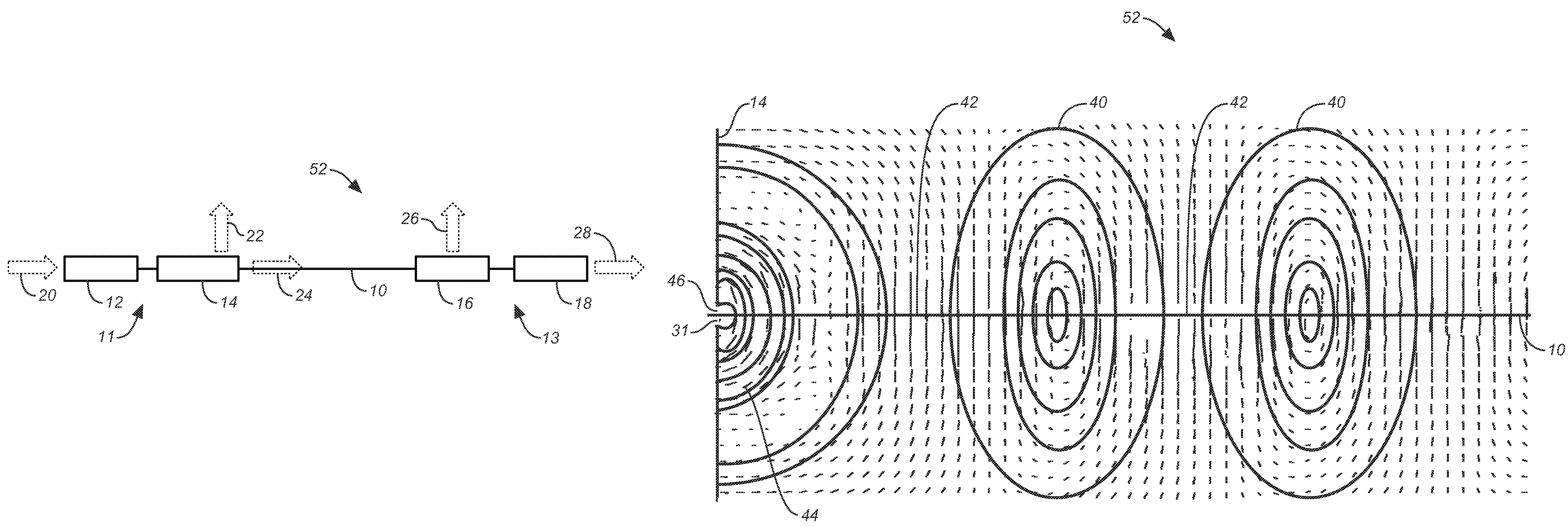
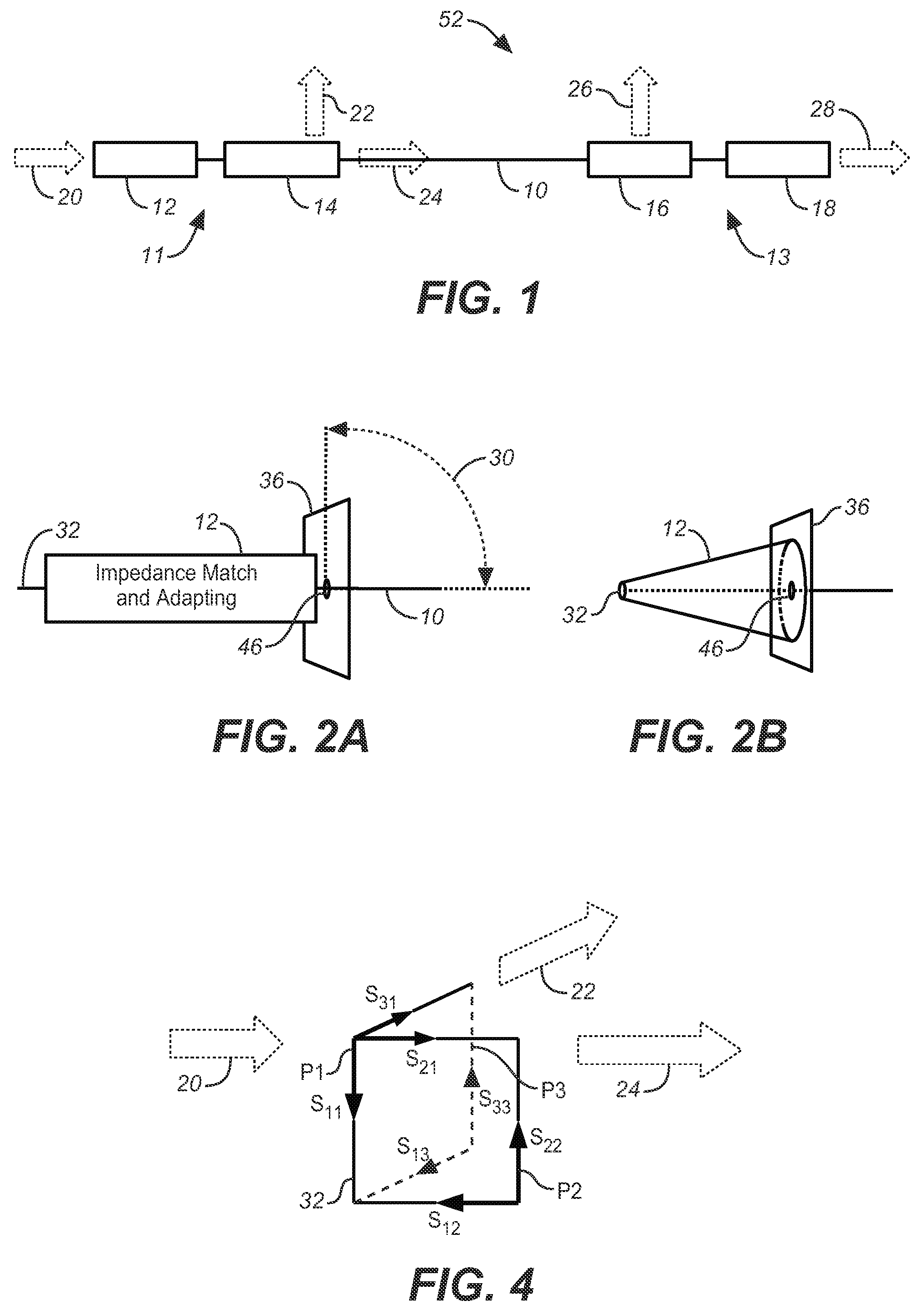
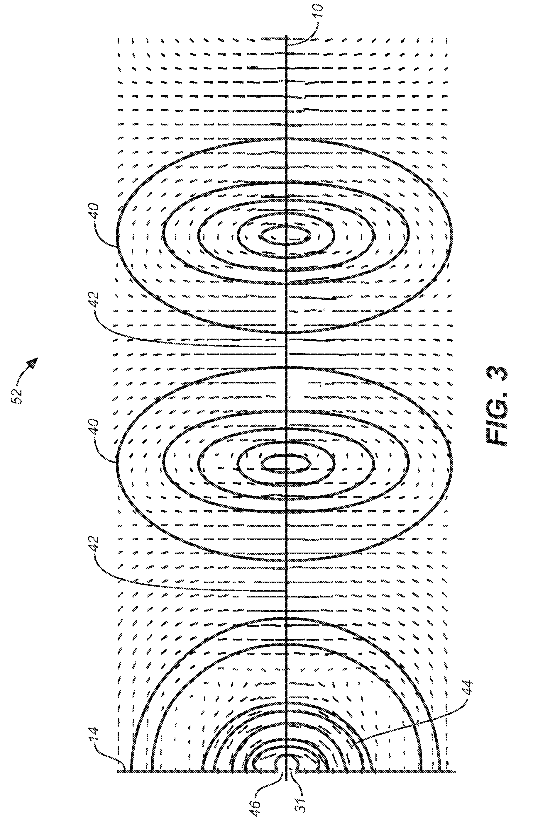
[0054]Referring now to FIGS. 1, 2A, 2E, 3, 4, 5A-5C, 6A, 7A-7C, 8A, 8B, 9A, 9B, 10-13, 14A and 14B, wherein like reference numerals refer to like components in the various views, there is shown a novel SWTL system for launching surface waves on a single conductor. FIG. 1 is a schematic view showing an embodiment of the present invention, which is a SWTL system comprising a first launcher 11 comprising an adapter 12 and mode converter 14 located at one end of a SWTL central conductor 10 which has its second end connected to a second launcher 13 comprising a second mode converter 16 and second adapter 18. The first and second launchers may be either identical or different in design.

[0055]The incident wave 20 may reach the first launcher either by way of propagation through or along a conventional type of transmission line or by radiation through a free space or dielectric medium. The launcher may also provide impedance transformation between the impedance of the incident wave to the i...


PUM


Abstract

A low attenuation surface wave transmission line system for launching surface waves on a bare and unconditioned conductor, such as are found in abundance in the power transmission lines of the existing power grids. The conductors within the power grid typically lack dielectric and special conditioning. Accordingly, the present invention includes a first launcher, preferably including a mode converter and an adapter, for receiving an incident wave of electromagnetic energy and propagating a surface wave longitudinally on the power lines. The system includes at least one other launcher, and more likely a number of other launchers, spaced apart from one another along the constellation of transmission lines. The system and associated electric fields along any given conductor are radially and longitudinally symmetrical.

Description

CROSS REFERENCES TO RELATED APPLICATIONS[0001]The present application is a continuation-in-part of U.S. Utility patent application Ser. No. 11 / 134,016, filed May 20, 2005, now abandoned, which claims the benefit of the priority date of U.S. Provisional Patent Application Ser. Nos. 60 / 573,531, flied May 21, 2004, and 60 / 576,354, filed Jun. 1, 2004.STATEMENT REGARDING FEDERALLY SPONSORED RESEARCH OR DEVELOPMENT[0002]Not applicable.THE NAMES OR PARTIES TO A JOINT RESEARCH AGREEMENT[0003]Not applicable.INCORPORATION-BY-REFERENCE OF MATERIAL SUBMITTED ON A COMPACT DISC[0004]Not applicable.BACKGROUND OF THE INVENTION[0005]1. Field of the Invention[0006]The present invention relates generally to surface wave transmission systems, and more particularly to a low loss system for launching surface waves over unconditioned lines such as power lines.[0007]2. Detailed Discussion of Related Art[0008]The original mathematical work underlying electromagnetic surface wave theory was done by Maxwell i...

Claims


Application Information

Patent Timeline
Patent Type & Authority Patents(United States)
IPC IPC(8): H01P3/10
CPCH01P3/10
Inventor ELMORE, GLENN E.
Owner CORRIDOR SYST INC
Why Eureka
Try Eureka