
Method and apparatus for creating interactive virtual tours

a virtual tour and interactive technology, applied in the field of interactive virtual tours, can solve the problems of tediousness and inaccuracy, severe limits to the practical value of the system, etc., and achieve the effect of fr

Inactive Publication Date: 2009-07-28
EKPAR FR EDUGHOM
View PDF12 Cites 5 Cited by
  • Summary
  • Abstract
  • Description
  • Claims
  • Application Information

AI Technical Summary

Benefits of technology

[0011]There are no moving parts. This permits both still image and video capture in a simple and cost-effective manner.
[0013]It is a further object of the present invention to provide a method and apparatus for creating spherical environment maps from images acquired using panoramic annular lens systems or simulations thereof and to provide fast polynomial-based interpolation means of correcting non-linear radial and tangential distortions as well as other distortions in the source panoramic images.This has the following advantages:
[0019]It is a further object of the present invention to provide a viewing engine implementing a means of permitting a user to interactively select any desired spherical environment map in the virtual tour package, and further, any desired view within the selected spherical environment map and performing perspective corrections on the selected view in order to present the user with a view window that is free from perspective distortions. The present invention permits a plurality of users to independently and simultaneously navigate and interact with the virtual tour package.
[0020]With regard to the viewing engine, it is an object of the present invention to provide a fast, simple, yet adequate (providing full pan, tilt and zoom controls) means of performing perspective correction of any selected portion of the spherical environment map.
[0021]It is also an object of the present invention to provide a means of constructing spherical environment maps from images captured with panoramic annular lens systems in a manner that permits panoramic images from panoramic annular lens systems with an asymmetrical vertical field of view (the maximum viewing angle above the horizon is not equal to the maximum viewing angle below the horizon) to be represented correctly.

Problems solved by technology

Apart from the obvious handicap of not being able to permit more than one user to comfortably navigate the remote scene, the inherent delay between the transmission of the orientation signal and the positioning of the camera to coincide with the desired orientation severely limits the practical value of this system.
Wide-angle imaging systems generally suffer from inherent (predictable) perspective distortion and so for the images they produce to be viewed comfortably by a human being, they need to be de-warped.
Several products (including Apple Computer's QTVR Authoring System) utilize image-stitching techniques to stitch several (possibly overlapping) conventional images in a tedious and error-prone (due to disparities in the characteristics of the individual image segments used) procedure to create cylindrical or spherical environment maps for the creation of virtual tours.
The system described in the '941 patent is also limited by the tediousness and inaccuracies of the image-stitching process.

Method used


Image

  • Method and apparatus for creating interactive virtual tours
  • Method and apparatus for creating interactive virtual tours
  • Method and apparatus for creating interactive virtual tours

Examples


Embodiment Construction

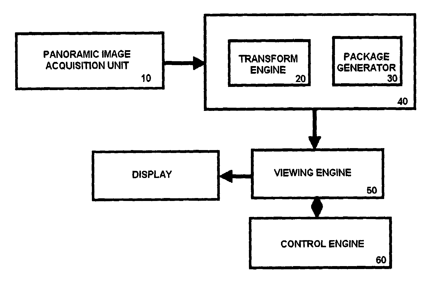
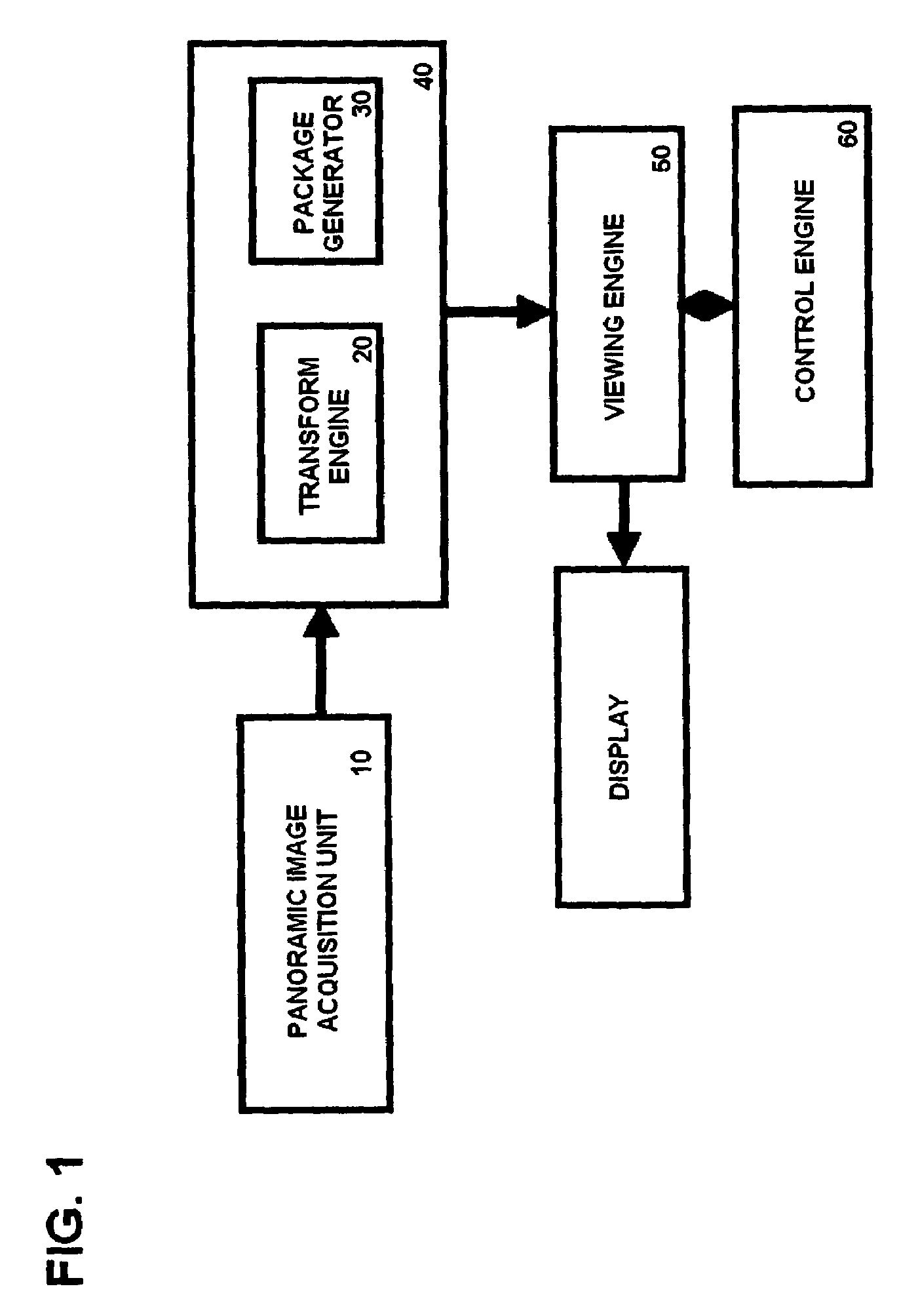
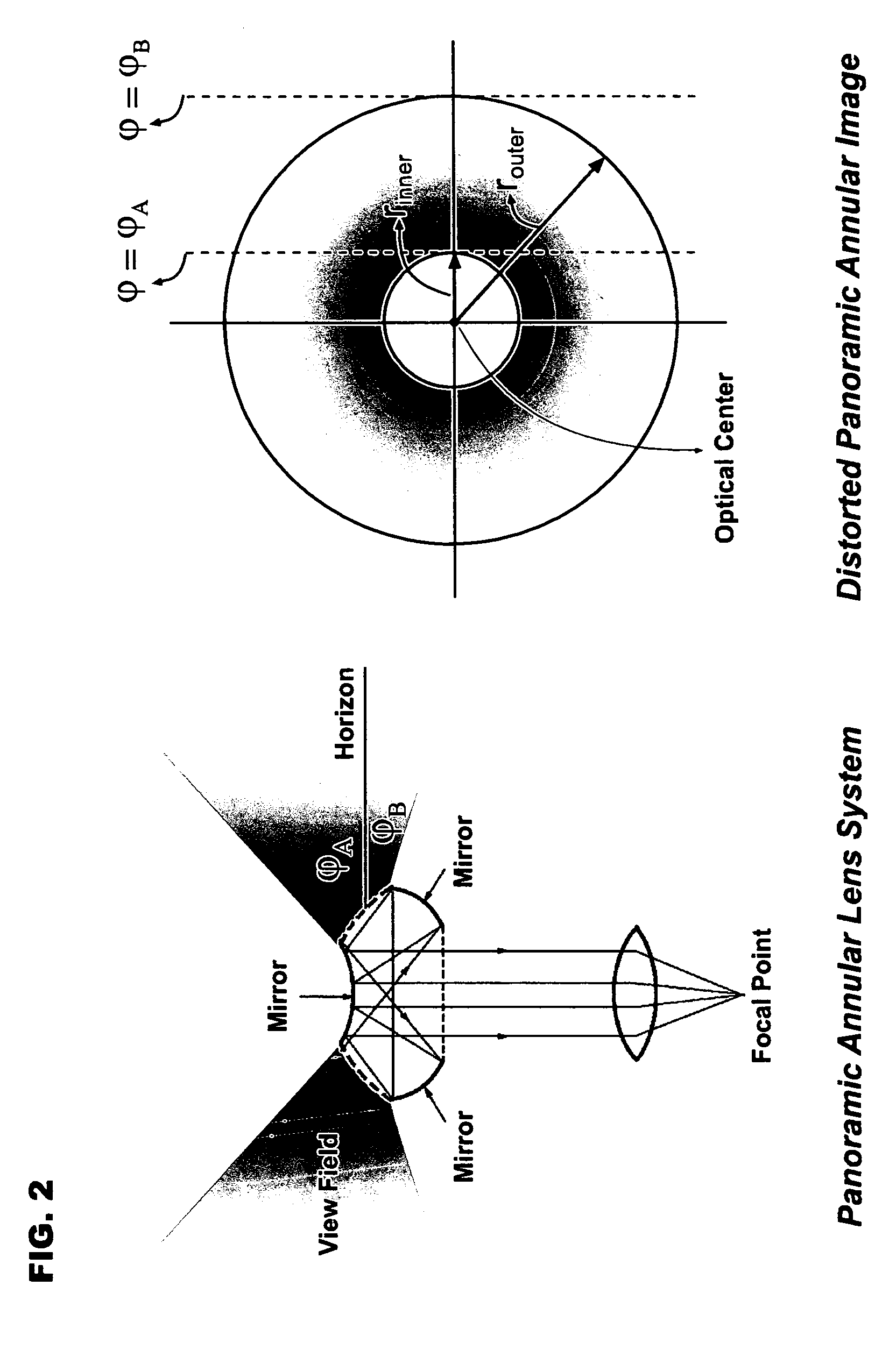
[0034]Referring now to FIG. 1, a block diagram showing the main components of the preferred embodiment of the present invention, the panoramic image acquisition unit 10 consists of a panoramic annular lens (such as the one disclosed in U.S. Pat. No. 4,566,763) and a still image or video camera. The panoramic image acquisition unit preferably contains digitizing circuitry that converts the panoramic annular images into a form suitable for processing on a computer. The output of the panoramic image acquisition unit can be used directly or stored in a suitable medium (tape, CD-ROM, DVD-ROM, etc) and retrieved for later use. The panoramic annular lens described in the '763 patent comprises a compact assembly of several reflecting and refracting surfaces. It generates a distorted, donut-shaped annular image as illustrated in FIG. 2 in a vertical cross-sectional view. The panoramic annular lens system has a 360-degree lateral field of view and a vertical field of view that is usually less...


PUM


Abstract

The present invention discloses a method and apparatus for creating interactive virtual tours. In one embodiment, panoramic imaging systems characterized by a 360-degree lateral field of view and a vertical field of view that is usually less than 180 degrees are utilized and polynomial-based interpolation algorithms are used to correct distortions in the input panoramic images, video or rendered scenes, permitting the use of an arbitrary panoramic imaging system characterized by the ability to generate a seamless 360-degree panoramic view of the imaged scene in each single image frame. The input panoramic images, video or rendered scenes are used to create spherical environment maps that are packaged into completely immersive (giving the impression of being there) virtual tours that are rendered on a display device by a viewing engine that corrects perspective distortions in the spherical environment maps contained in the virtual tour packages and permits a plurality of viewers to view any portion of any of the panoramic scenes in the virtual tour package in a manner that is free from distortions. The present invention also discloses a control engine for representing the individual panoramic scenes contained in the virtual tour package in multi-dimensional space and / or time and for transmitting control signals to the viewing engine that cause the viewing engine to render any particular panoramic scene selected by the viewer and any view window on the selected panoramic scene desired by the viewer. Furthermore, the control engine communicates bi-directionally with the viewing engine and provides a means of indicating which particular panoramic scene is currently viewed by the viewing engine as well as a means of indicating what portion of the selected panoramic scene is currently displayed by the viewing engine.

Description

CROSS-REFERENCE TO RELATED APPLICATIONS[0001]This U.S. Non-Provisional Application claims the benefit of U.S. Provisional Application Ser. No. 60 / 432,459, filed on Dec. 9, 2002, herein incorporated by reference.BACKGROUND OF THE INVENTION[0002]1. Field of the Invention[0003]The present invention relates generally to the fields of image processing for correction of image distortion produced by a wide-angle lens or simulation of a wide-angle lens and the creation of navigable virtual tours comprising primarily of panoramic images or video. In one embodiment, the invention relates to a system permitting the creation of immersive spherical environment maps from the class of panoramic imaging systems characterized by a 360-degree lateral field of view and a vertical field of view that is usually less than 180 degrees and the creation of navigable virtual tours comprising primarily of such spherical environment maps. The invention permits the use of an arbitrary lens in the aforementioned...

Claims


Application Information

Patent Timeline
Patent Type & Authority Patents(United States)
IPC IPC(8): H04N5/232G06T3/00H04N5/225H04N5/262
CPCG06T3/0062H04N5/2628H04N5/2259H04N23/58G06T3/12
Inventor EKPAR, FRANK EDUGHOM
Owner EKPAR FR EDUGHOM
Learn More