Ridge waveguide optical sensor incorporating a Bragg grating

a bragg grating and optical sensor technology, applied in the field of bragg grating sensor, can solve the problems of affecting the spatial accuracy of the temperature measurement and the mechanical strength of the device, the inability to accurately measure the temperature, and the inability to adjust the sensitivity of the sensor,

Inactive Publication Date: 2009-07-28
NAT RES COUNCIL OF CANADA
View PDF6 Cites 8 Cited by
  • Summary
  • Abstract
  • Description
  • Claims
  • Application Information

AI Technical Summary

Problems solved by technology

Measurements from Bragg grating based refractometers however often can be distorted by fluctuations in the ambient temperature.
These prior art gratings are instructive and provide a useful function, however they are known to suffer from some limitations in terms of the spatial accuracy of the temperature measurement and the mechanical strength of the device.
The requirement to improve the sensitivity of the fiber grating refractometers by polishing and etching as taught by Asseh et al. leads to devices that are mechanically weak and fragile.
Because of the flexible nature of optical fibers however, the tilted grating refractometers suffer from the limitation that the cladding mode resonances, which are used to monitor the temperature, are sensitive to physical changes across the fiber cross-section such as shear strains arising from fiber bending.
Aside from the limitations resulting from fiber flexibility as stated for the tilted grating refractometer, the sampled fiber Bragg grating refractometer has the additional limitation that the spectral response of the cladding guided long period grating resonance is spectrally broad (>10 nm) making high accuracy measurements of small wavelength shifts difficult.
These prior art planar waveguide gratings provide a useful function, however they are known to suffer from some limitations.
In the case of Veldhuis et al. an etch process is also required for the Bragg grating fabrication which is an exacting labour intensive process.
However, the device was sensitive to temperature change as the Bragg wavelength shifted with temperature (˜11 pm / ° C. in silica waveguides).

Method used


Image

  • Ridge waveguide optical sensor incorporating a Bragg grating
  • Ridge waveguide optical sensor incorporating a Bragg grating
  • Ridge waveguide optical sensor incorporating a Bragg grating

Examples


Embodiment Construction

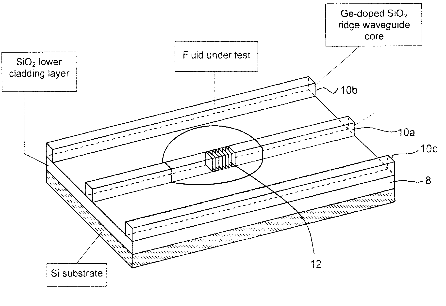
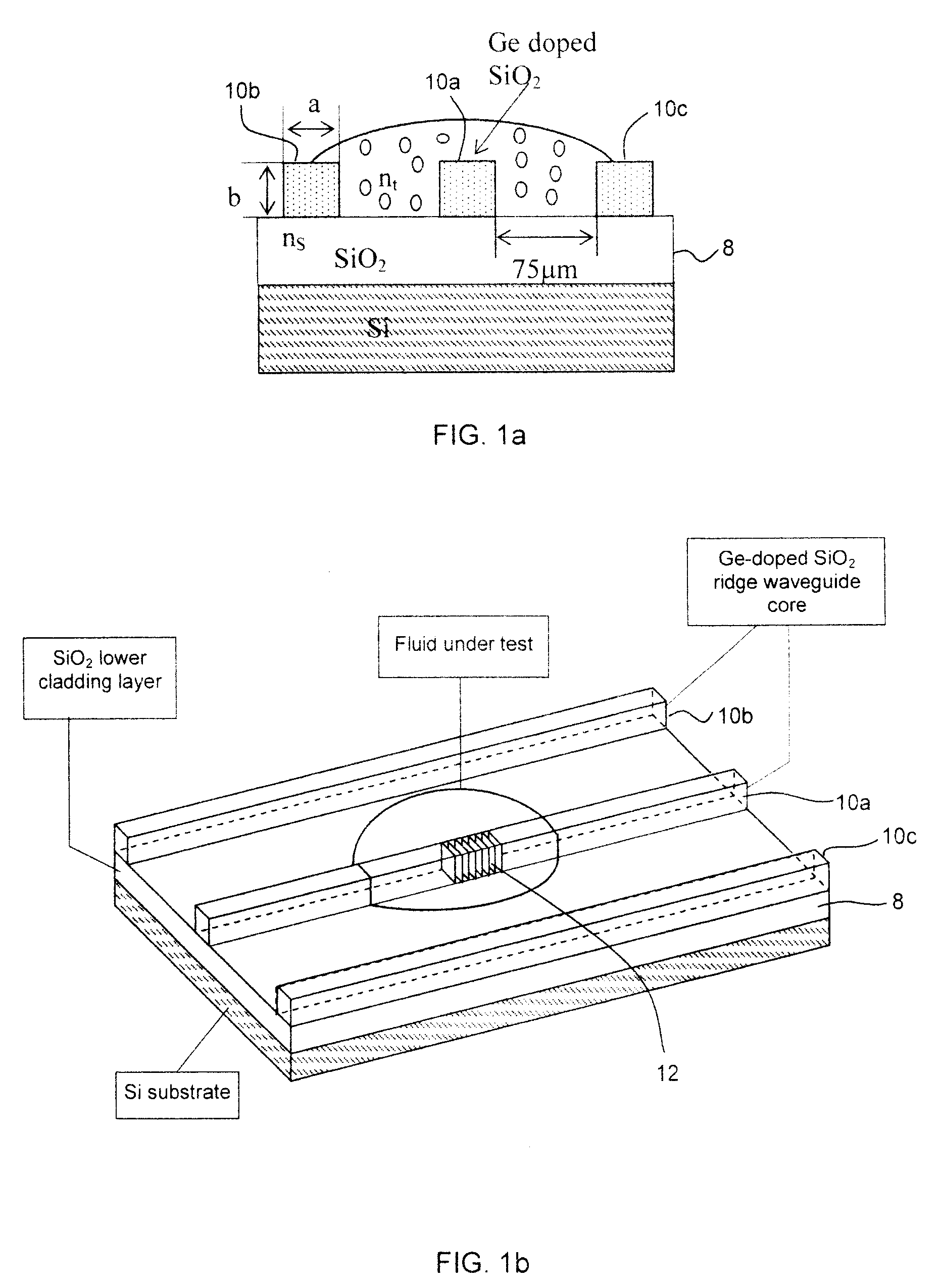
[0030]Referring now to FIG. 1a an open-top rib or ridge waveguide is as shown. FIG. 1b shows a cross section of the structure shown in FIG. 1a. More particularly a center ridge waveguide 10a absent a top cladding layer contains a photo-induced Bragg grating 12 supported by a cladding layer 8 which is tested as a refractometer by coupling a light source into the end of the waveguide. Two adjacent waveguides 10b and 10c also supported by the cladding layer 8 are optionally provided to act as a barrier and to partially prevent the liquid from flowing away from the waveguide 10a containing the grating. The adjacent waveguides 10b and 10c do not contribute to the device performance. The guided light provided to the center waveguide 10a couples evanescently into the surrounding liquid through the top and sides of the waveguide. The three waveguides shown in FIGS. 1a and 1b have the same width versus height dimension a×b and are separated by 75 μm. Three different sets of waveguide dimensi...


PUM


Abstract

An optical sensor for sensing information relating to an analyte liquid or gas, has a a planar substrate having a refractive index nc. The planar substrate supports a ridge waveguide having an unclad top portion having a refractive index nr. The substrate serves as cladding layer for the ridge waveguide at a location where the ridge waveguide contacts the substrate. A Bragg grating inscribed in the ridge waveguide has two modes for providing information relating to both temperature and refractive index of the surrounding analyte liquid or gas. A cladding mode has a different response to the analyte when compared to a Bragg resonance response. Both modes have a same reaction to temperature, wherein said Bragg grating is formed within the unclad region of ridge waveguide, wherein nc.<nr. Advantageously multiple parameters can be sensed using only a single Bragg grating.

Description

CROSS-REFERENCE TO RELATED APPLICATIONS[0001]The present invention claims priority from U.S. Provisional Patent Application No. 60 / 954,854 filed Aug. 9, 2007, which is incorporated herein by reference.FIELD OF THE INVENTION[0002]The present invention relates to a sensing apparatus and method for measurement of refractive index of a surrounding liquid or gas, and more particularly to a Bragg grating sensor inscribed in a ridge waveguide. The sensing apparatus is substantially insensitive to fluctuations in temperature.BACKGROUND OF THE INVENTION[0003]With their miniature size, non-invasive and rapid detection, a waveguide Bragg grating refractometric sensor can be a useful tool for chemical analysis and biomedical testing, where the evanescent field of the fundamental mode propagating in a waveguide containing a Bragg grating can interact with liquids and gases surrounding the waveguide in order to measure small changes in the refractive index of the surrounding liquid. Measurements ...

Claims


Application Information

Patent Timeline
Patent Type & Authority Patents(United States)
IPC IPC(8): G02B6/00G02B6/26
CPCG01N21/4133G02B2006/12107G01N2021/458
Inventor DAI, XIAOLIMIHAILOV, STEPHEN J.WALKER, ROBERT B.BLANCHETIERE, CHANTALCALLENDER, CLAIREDING, HUIMINLU, PINGGROBNIC, DANSMELSER, CHRISTOPHER W.CUGLIETTA, GINO
Owner NAT RES COUNCIL OF CANADA
Why Eureka
Try Eureka