
Enhanced diaphragm for pressure sensing system and method

a technology of pressure sensing system and diaphragm, which is applied in the direction of instruments, catheters, angiography, etc., can solve the problems of reducing the desirability of the mems diaphragm directly contacting, affecting the accuracy of pressure measurements of sampled fluid, and not being compatible with the particular environment and/or the fluid being measured

Inactive Publication Date: 2009-08-04
PACESETTER INC
View PDF6 Cites 21 Cited by
  • Summary
  • Abstract
  • Description
  • Claims
  • Application Information

AI Technical Summary

Problems solved by technology

Unfortunately, temperature changes can cause the intermediary fluid to expand or contract at a different rate than pertinent components of the housing thereby inducing pressure changes in the intermediary fluid unrelated to pressure status of the sampled fluid and consequently, affecting accuracy of pressure measurements of the sampled fluid.
In some applications of miniature pressure sensor systems, a MEMS diaphragm may not be compatible with the particular environment and / or the fluid being measured such as intraluminal fluids found in biological environments like with blood flows in vascular structures.
These situations can reduce the desirability of the MEMS diaphragm directly contacting the fluid being measured.
Selection of conventional diaphragms used in non-miniature pressure sensor systems for use as an external diaphragm in miniature pressure sensor systems involving MEMS can be problematic.
Further, these industrial applications typically involve a wide range of pressures, which allows such large sized industrial diaphragms to impart a very small error in pressure measurement relative to the range of pressures being measured.
In applications involving miniature pressure sensor systems, such as with vascular structures, where the size of a pressure sensor system is relatively small and where measured pressures have small ranges and / or values, use of conventional diaphragms for an external diaphragm raise scaling issues when going from the larger scale applications to the smaller scale applications.
The operational life spans of the coatings tend to be short due to the coatings so are not appropriate where sensor elements require long-term protection from corrosive body fluids.
In addition, these conventional coatings expose sample intravascular blood to surfaces that are not fully hemocompatible, such as found with the silicone or fluorosilicone gel materials used for the coatings, which can lead to thrombus (clot) formation within a vascular structure hosting such a miniature pressure sensor system.
An undesirable geometry for fluid flow applications includes rough, non-hydrodynamic surfaces that can induce shearing motion within a blood flow thereby introducing a potential activation mechanism of a coagulation cascade, leading to thrombus (clot) formation.

Method used


Image

  • Enhanced diaphragm for pressure sensing system and method
  • Enhanced diaphragm for pressure sensing system and method
  • Enhanced diaphragm for pressure sensing system and method

Examples


Embodiment Construction

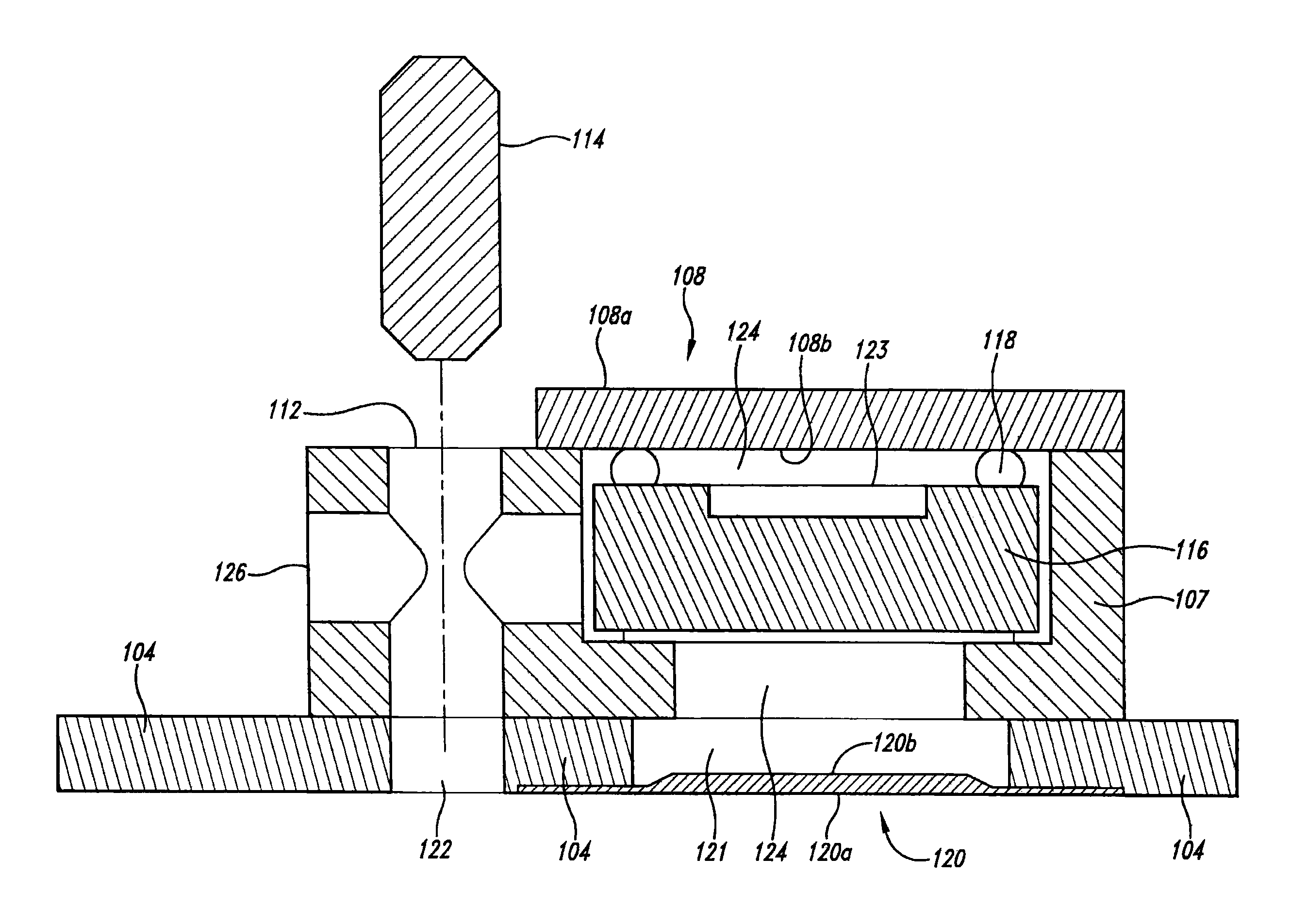
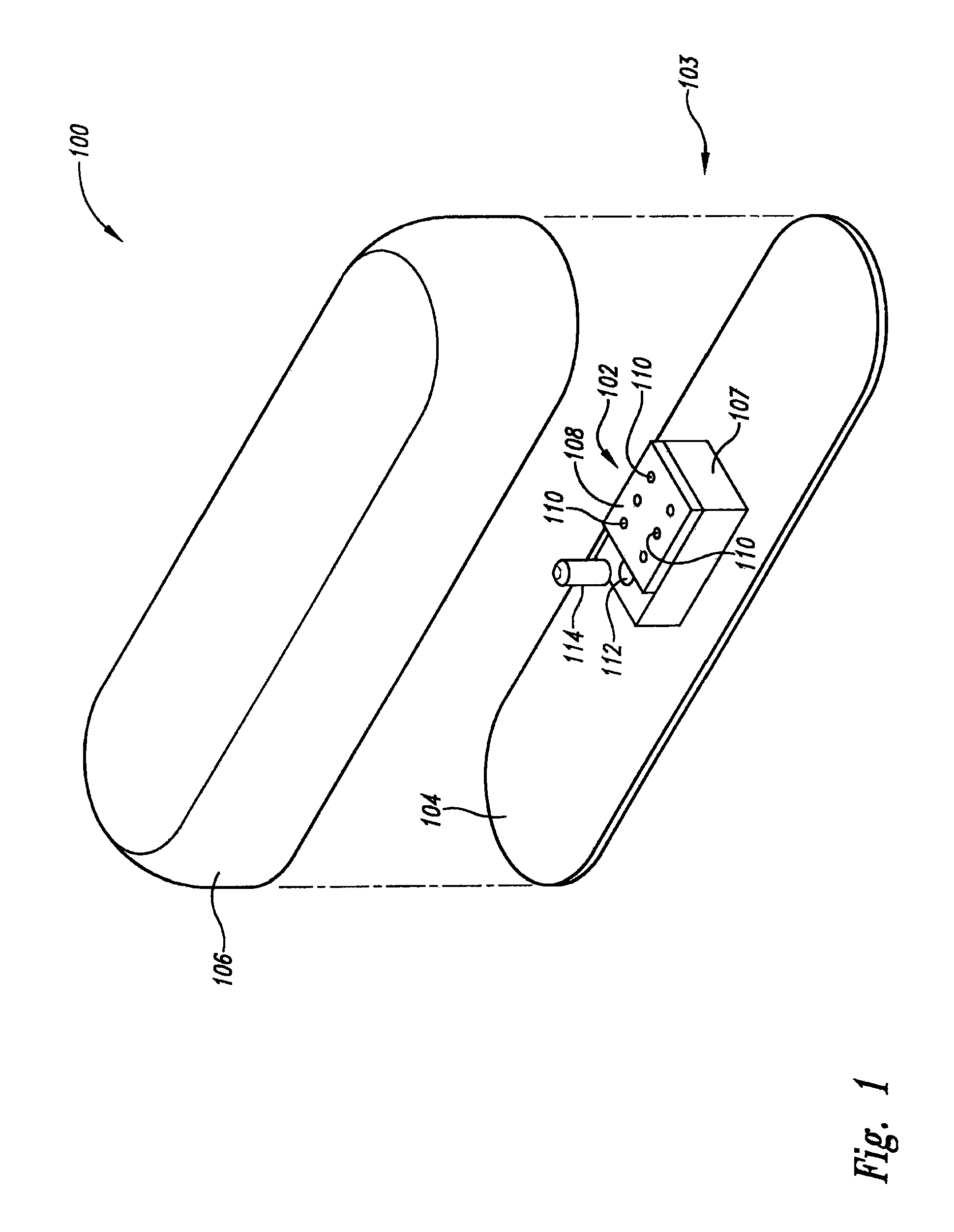
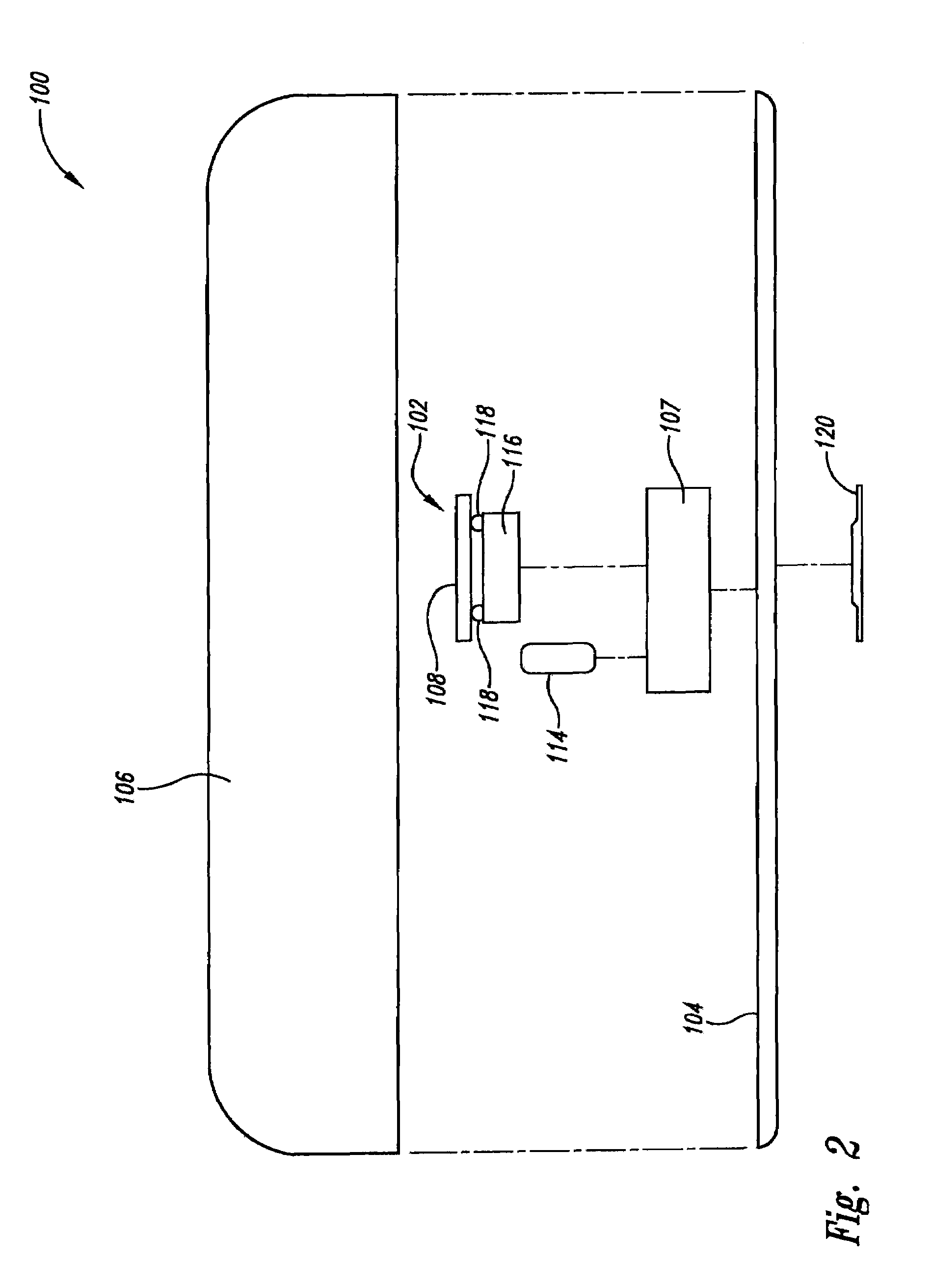
[0027]An enhanced pressure sensing system and method of miniature size, such as for implantation in a biological structure such as a lumen, vessel, or other tubular structure, is discussed herein that addresses issues involved with accurate and prolonged measurement of fluid pressure, such as of blood flowing in a vascular structure. The issues include providing at least close to hermetic isolation between a sampled fluid and a pressure sensor, providing high compliance levels of the miniature pressure sensor system with the host environment (such as a vascular structure containing flowing blood), and maintaining accurate correspondence between internal intermediary fluid pressure and sampled fluid pressure, so that sampled fluid pressure state is accurately transferred to the internal sensor.

[0028]Implementations of external diaphragms are incorporated into the enhanced pressure sensing system to address such issues. For instance, some implementations of the external diaphragm incl...


PUM

PropertyMeasurementUnit
diameteraaaaaaaaaa
pressureaaaaaaaaaa
pressureaaaaaaaaaa

Abstract

An enhanced pressure sensing system and method use an external diaphragm to address issues involved with accurate and prolonged measurement of fluid pressure, such as of blood flowing in a vascular structure. Some external diaphragms include a metallized layer or other highly impermeable layer to furnish a high degree of seal at least near to hermetic grade. As temperature of the intermediary fluid changes, the external diaphragm is able to move in a direction that minimizes differential pressure across the external diaphragm over an operational temperature range thereby reducing pressure change of the intermediary fluid due to change in temperature of the intermediary fluid. Relatively smooth hydrodynamic surfaces can be used as well as a bi-layer construction.

Description

BACKGROUND OF THE INVENTION[0001]1. Field of the Invention[0002]The present invention is directed generally to pressure sensor systems.[0003]2. Description of the Related Art[0004]A miniature pressure sensor system can include a housing with an external diaphragm that directly contacts a sampled fluid, a sensor (enclosed by the housing) that is not in direct contact with the sampled fluid, and an internal intermediary fluid (contained within the housing) that contacts the external diaphragm and also contacts the sensor to allow the sensor to measure pressure of the sampled fluid. In order to accurately transfer pressure from the sampled fluid to the sensor, among other things, the external diaphragm must be as compliant with the sampled fluid as possible. Unfortunately, temperature changes can cause the intermediary fluid to expand or contract at a different rate than pertinent components of the housing thereby inducing pressure changes in the intermediary fluid unrelated to pressur...

Claims


Application Information

Patent Timeline
Patent Type & Authority Patents(United States)
IPC IPC(8): G01L7/08
CPCA61B5/0215G01L19/04G01L19/0046A61B2562/0247A61B2562/028
Inventor KEILMAN, GEORGE W.JOHNSON, TIMOTHY
Owner PACESETTER INC
Learn More