
Tool pots mounting structure for a tool magazine

Inactive Publication Date: 2009-08-04
NEW GIFU ENTERPRISE
View PDF9 Cites 7 Cited by
  • Summary
  • Abstract
  • Description
  • Claims
  • Application Information

AI Technical Summary

Benefits of technology

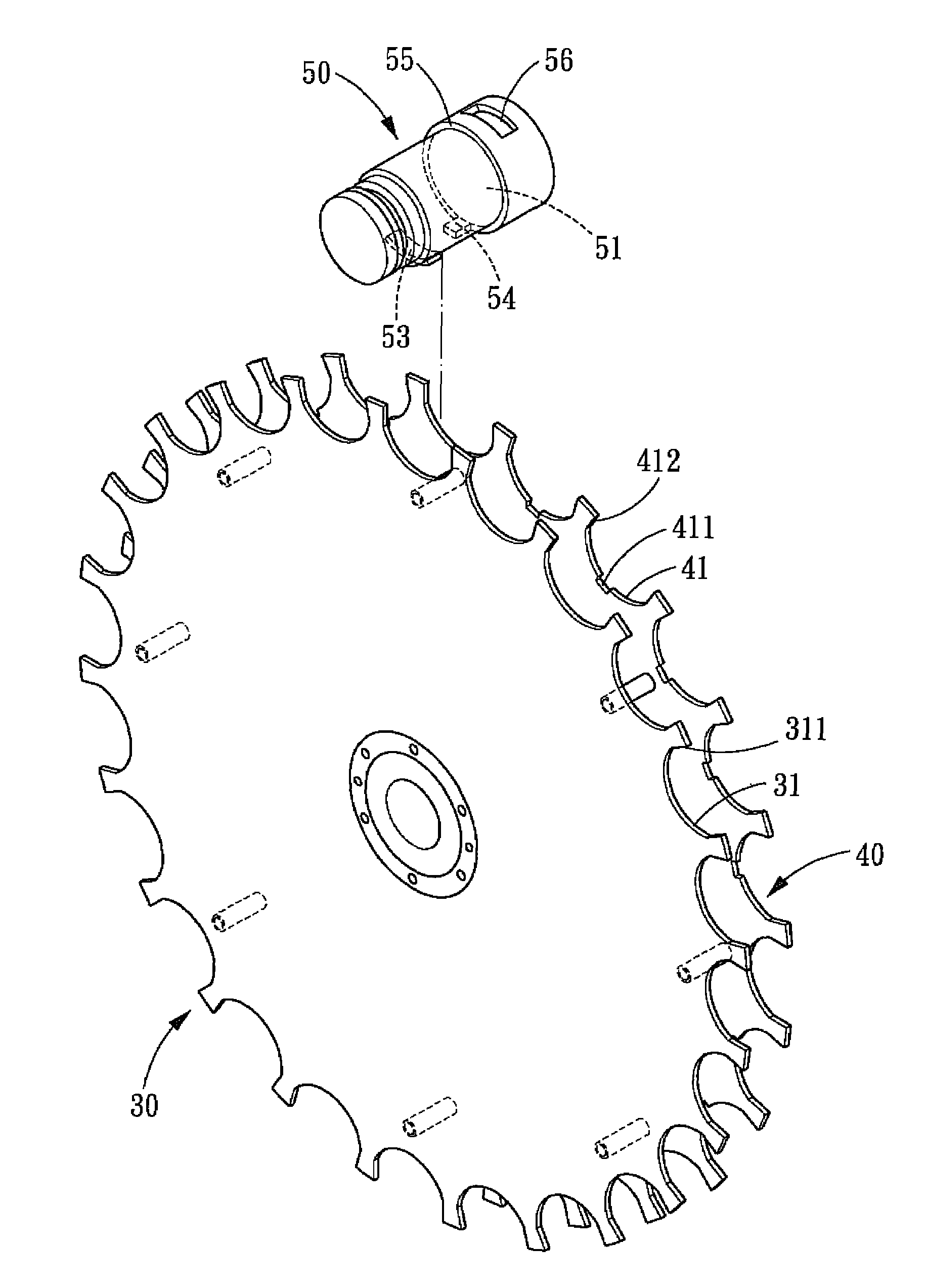
[0009]The primary objective of the present invention is to provide a tool pots mounting structure for a tool magazine. The tool pots inside the tool magazine can be engaged into the engaging notches of the first and second mounting discs directly without using locking means. In assembly of the respective tool pots to the two mounting discs, the respective tool pots can be directly placed into the engaging notches of the two mounting discs without any bolts, pivots or pivotal structures, and without using tools, such as power screwdriver, to assemble the tool pots. Hence, not only is the assembly process simplified, the assembly cost is reduced, but also the follow-up maintenance work is also reduced. For the whole field of tool magazine manufacturing, it undoubtedly is a revolutionary technological breakthrough.
[0010]The further objective of the present invention is to provide simply structured tool pots mounting structure for a magazine, wherein a tool change device is disposed at one side of a tool change port of the tool magazine, by using a pressure cylinder to drive a drive member to move, and further driving a pivotal member to clamp the desired tool pot, the tool pot can be pivoted to disengage from the first and second mounting discs. By such arrangements, the present invention can carry out the tool change operation with only a single tool change device. Hence, not only is the cost of the present invention considerably reduced, but also the assembly process is also much simplified.

Problems solved by technology

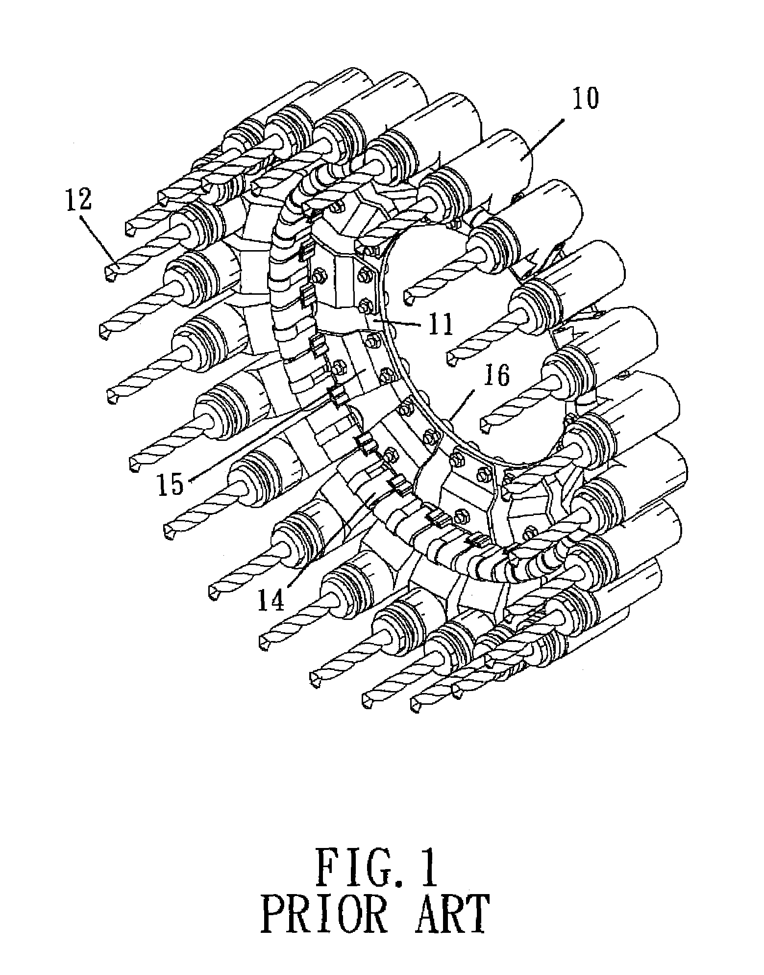
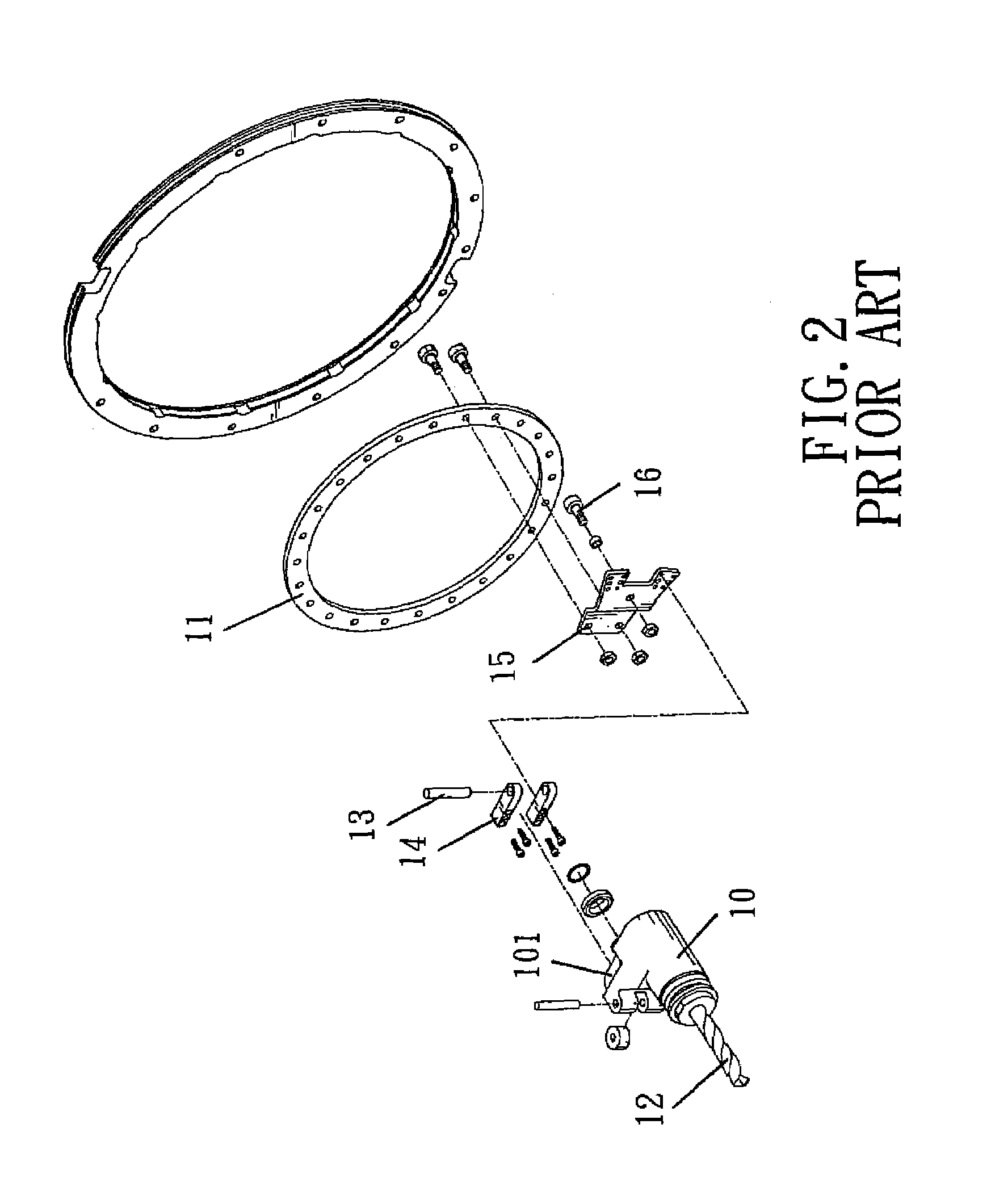
Therefore, in assembly of the mounting disc and the respective tool pots, it must assemble the respective tool pots, pivots, pivot structures, and bolts to the mounting disc, respectively, and such assembly operation should be repeated for 24 times. Not only is the number of the components large, the cost of the components is pretty high, and the assembly cost is also very high, but also the follow-up maintenance work will be very complicated.

Method used


Image

  • Tool pots mounting structure for a tool magazine
  • Tool pots mounting structure for a tool magazine
  • Tool pots mounting structure for a tool magazine

Examples


Embodiment Construction

[0022]The present invention will be clearer from the following description when viewed together with the accompanying drawings, which show, for purpose of illustrations only, the preferred embodiment in accordance with the present invention.

[0023]Referring to FIGS. 3-9, a tool pots mounting structure for a tool magazine in accordance with a preferred embodiment of the present invention is shown and comprises: a tool magazine 20, a first mounting disc 30, a second mounting disc 40, a plurality of tool pots 50, a tool change device 60. The tool pots inside the tool magazine can be engaged into the engaging notches of the first and second mounting discs directly without using locking means, and then the tool change device is used to carry out tool change operation.

[0024]The tool magazine 20 is provided with a protection housing 21 for accommodation of respective components of the tool magazine. On the inner surface of the housing 21 are disposed a plurality of rails 22 which are made o...


PUM


Abstract

A tool pots mounting structure for a tool magazine, wherein the tool pots inside can be engaged into the engaging notches of the first and second mounting discs directly without using without any bolts, pivots or pivotal structures, and without using tools, such as power screwdriver, to assemble the tool pots. Hence, not only is the assembly process simplified, the assembly cost is reduced, but also the follow-up maintenance work is also reduced. A tool change device is disposed at one side of a tool change port of the tool magazine, by using a pressure cylinder to drive a drive member to move, and further driving a pivotal member to clamp the desired tool pot, the tool pot can be pivoted to disengage from the first and second mounting discs. By such arrangements, the tool change operation can be carried out by only a single tool change device. Hence, not only is the cost considerably reduced, but also the assembly process is also much simplified.

Description

BACKGROUND OF THE INVENTION[0001]1. Field of the Invention[0002]The present invention relates to a tool pots mounting structure for a tool magazine, and more particularly to a tool pots mounting structure which uses two mounting discs to flexibly positioning the tool pots, and a single tool change device serves to perform tool change operation.[0003]2. Description of the Prior Art[0004]Machining center is capable of performing various machining operations by timely and selectively using different cutting tools, and the tools storing and changing operation of such a machining center is achieved by a tool magazine.[0005]The present invention is going to discuss the tool magazine which is used for mounting various kinds of tool pots and mounting disc. With reference to FIGS. 1 and 2, which show the tool pots 10, the mounting disc 11 and the tools 12 of a conventional tool magazine. The tool pots 10 are used to receive the tools 12, and the respective pots 10 and the mounting disc 11 ar...

Claims


Application Information

Patent Timeline
IPC IPC(8): B23Q3/157
CPCB23Q3/15526B23Q3/15746Y10T483/1836Y10T483/1882Y10T483/115Y10T483/18Y10T483/1864B23Q2003/15532
Inventor LIU, TONY
Owner NEW GIFU ENTERPRISE
Learn More