Fast power-on detect circuit with accurate trip-points

a detection circuit and trip-point technology, applied in the field of fast power-on detection circuits, can solve the problems of poor trip-point accuracy, power detectors based on bandgap reference, and inability to meet the most speed requirements, etc., and achieve the effect of accurate trip-point, fast response, and narrow variation

Active Publication Date: 2009-08-04
CYPRESS SEMICON CORP
View PDF7 Cites 5 Cited by
  • Summary
  • Abstract
  • Description
  • Claims
  • Application Information

AI Technical Summary

Benefits of technology

[0008]According to the present invention, a power-on detect circuit (power detector) has an accurate trip-point and very narrow variation across the process and temperature corners. The trip-point of the power detector has the accuracy of the bandgap reference voltage. The power detector has a fast response that allows users power-up and power-down the circuit quickly. The trip-points are determined solely by the voltage level of the power supply; thus, it reliably trips the circuit independently from the power-up and power-down speeds.

Problems solved by technology

There are accurate power detectors based on the bandgap reference, but they are slow because of the slow response of the operational amplifiers inside the bandgap reference.
Thus, this kind of power detector cannot meet most speed requirements.
There are timing based power detectors based on RC delay or based on CMOS threshold voltage, but they are very poor in the accuracy of the trip-points.
Trying to combine these types of power detectors to achieve both high speed and high accuracy is difficult and unreliable because that involves coordinating between voltage levels and power-up and power-down speeds, and the power-up and power-down profiles are essentially uncertain in the real world.
Having a reliable power-on reset circuit is critically important if an incorrect initial state of the circuit in a nonvolatile memory may accidentally cause an access to the memory at a low supply voltage and result in data loss.
In contrast to the first two types of power-on reset circuits, the bandgap-based power-on reset circuits have narrow variations, but their responses are slow and cannot meet the speed requirements for most integrated circuit applications.
Attempting to combine these various types of power detectors to achieve both high speed and high accuracy is difficult and unreliable because that involves coordinating voltage levels and power-up and power-down speeds, and the power-up and power-down profiles are essentially uncertain in the real world.
As mentioned above, the long settling time of the operational amplifier limits the power-up speed.
These kinds of circuits have good temperature compensation and provide accurate trip-points, but they are not applicable for fast power-up due to long settle time of the operational amplifiers.

Method used


Image

  • Fast power-on detect circuit with accurate trip-points
  • Fast power-on detect circuit with accurate trip-points
  • Fast power-on detect circuit with accurate trip-points

Examples


first embodiment

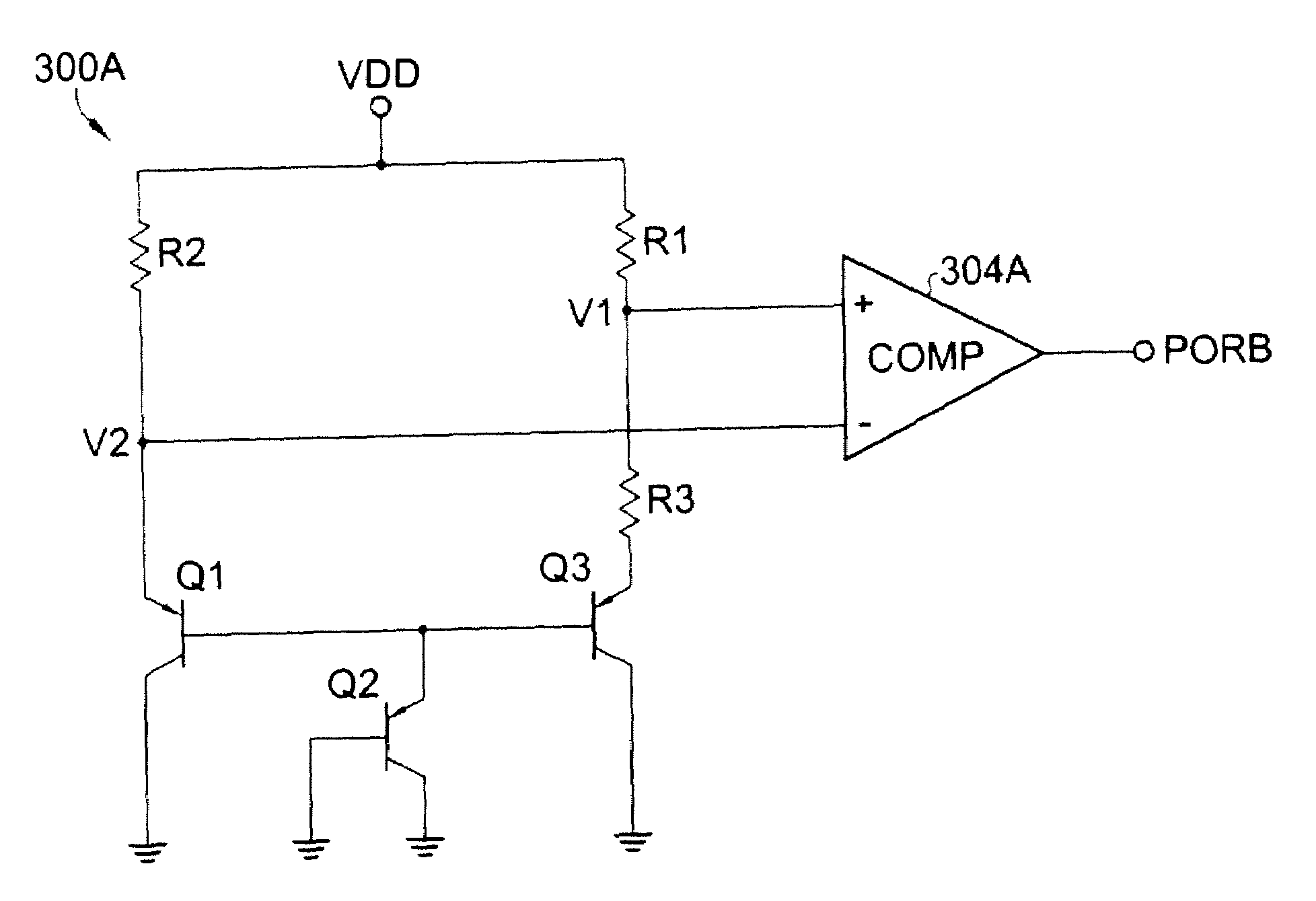
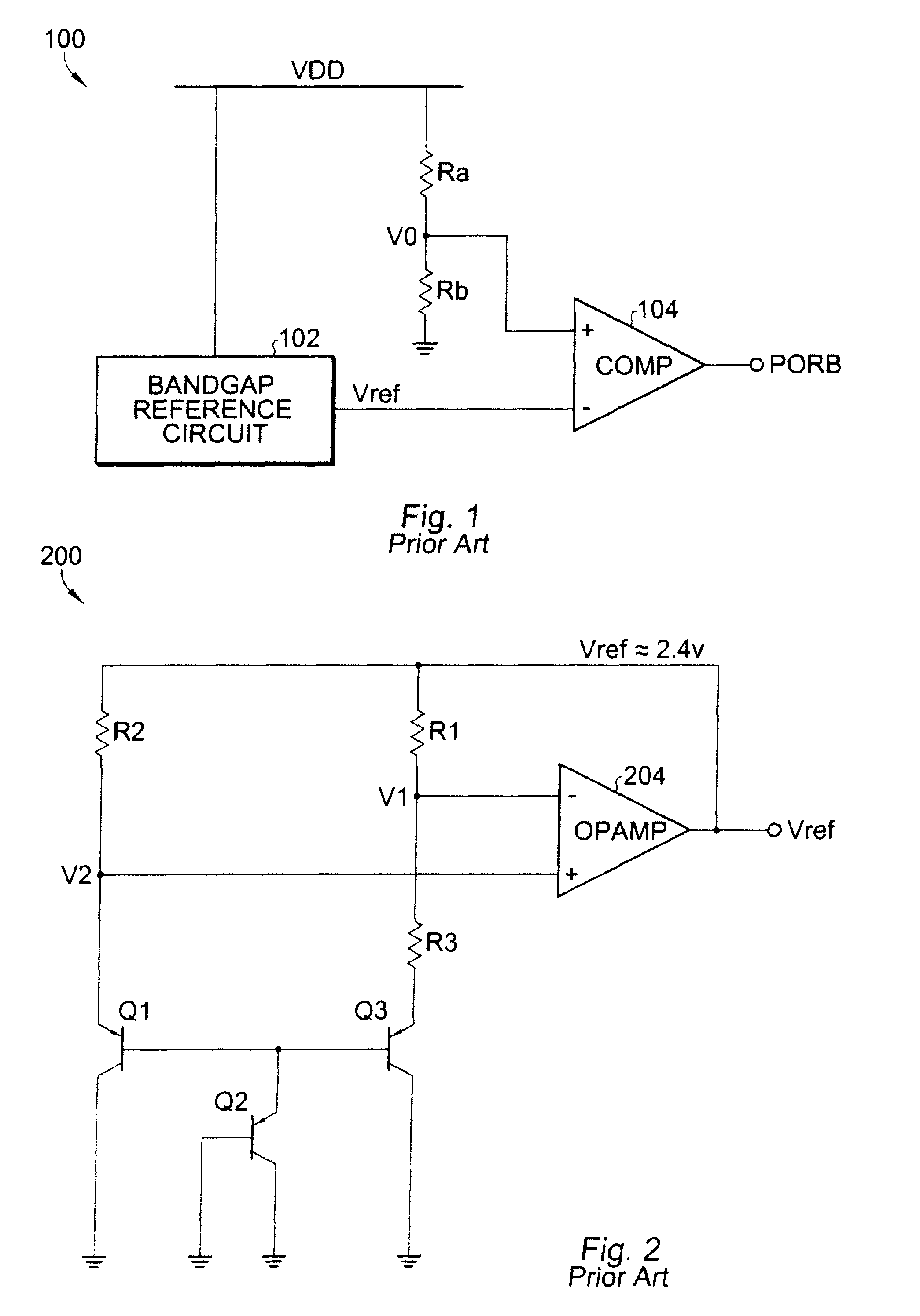
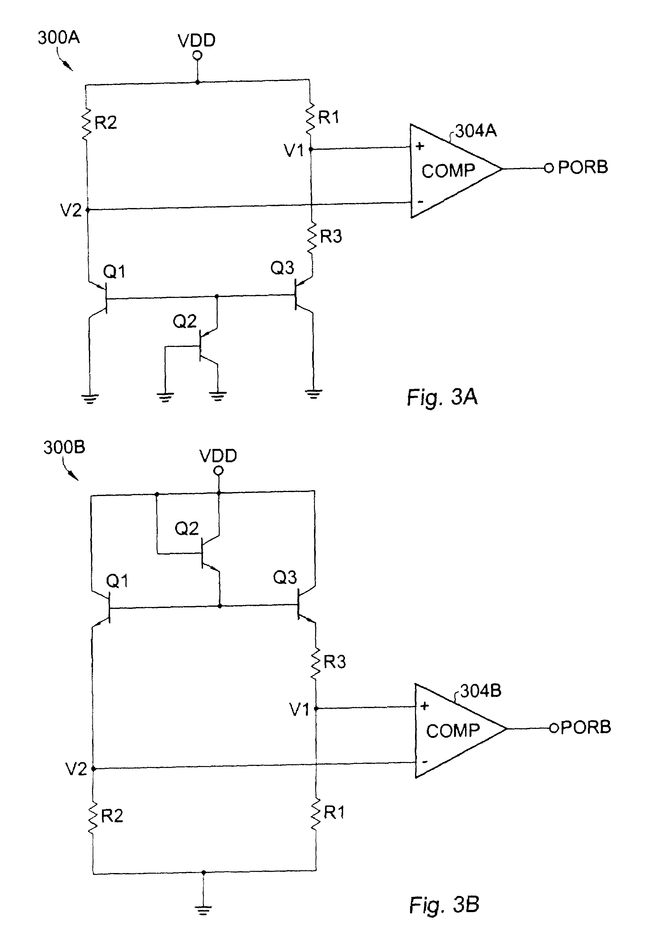
[0020]Referring now to FIG. 3A, a schematic diagram is shown of the power-on reset circuit 300A according to the present invention. Operational amplifier 204 from prior art FIG. 2 is replaced by a fast comparator 304A, and the “top nodes” of resistors R1 and R2 (which were previously coupled to the reference voltage Vref at the output of operational amplifier 204 in the bandgap reference circuit 200 in FIG. 2) are now tied to the power supply voltage VDD.

[0021]Power-on reset circuit 300A includes a first PNP transistor Q1 having an emitter, a base, and a collector coupled to ground; a second transistor Q2 having an emitter coupled to the base of the first transistor, and a base and collector coupled to ground; a third transistor Q3 having an emitter, a base coupled to the base of the first transistor, and a collector coupled to ground; a first resistor R1 coupled between the VDD power supply and an internal node; a second resistor R2 coupled between VDD and the emitter of the first ...

second embodiment

[0022]Referring now to FIG. 3B, the power-on reset circuit is shown according to the present invention. Power-on reset circuit 300B includes a first NPN transistor Q1 having an emitter, a base, and a collector coupled to VDD; a second transistor Q2 having an emitter coupled to the base of the first transistor, and a base and collector coupled to VDD; a third transistor Q3 having an emitter, a base coupled to the base of the first transistor, and a collector coupled to VDD; a first resistor R1 coupled between ground and an internal node; a second resistor R2 coupled between ground and the emitter of the first transistor; a third resistor R3 coupled between the internal node and the emitter of the third transistor; and a comparator 304B having a positive input coupled to the internal node and a negative input coupled to the emitter of the first transistor for generating a power-on reset signal PORB.

[0023]In circuit 300A shown in FIG. 3A, PNP diode-connected transistor Q2 can be replac...


PUM


Abstract

A power-on reset circuit includes a first PNP transistor having an emitter, a base, and a collector coupled to ground; a second PNP transistor having an emitter coupled to the base of the first transistor, and a base and collector coupled to ground; a third PNP transistor having an emitter, a base coupled to the base of the first transistor, and a collector coupled to ground; a first resistor coupled between VDD and an internal node; a second resistor coupled between VDD and the emitter of the first transistor; a third resistor coupled between the internal node and the emitter of the third transistor; and a comparator having a first input coupled to the internal node and a second input coupled to the emitter of the first transistor for generating a power-on reset signal.

Description

BACKGROUND OF THE INVENTION[0001]The present invention is related to power-on detect circuits, and more particularly, to a fast power-on detect circuit suitable for use in nonvolatile memory and other integrated circuits.[0002]There are accurate power detectors based on the bandgap reference, but they are slow because of the slow response of the operational amplifiers inside the bandgap reference. Thus, this kind of power detector cannot meet most speed requirements. There are timing based power detectors based on RC delay or based on CMOS threshold voltage, but they are very poor in the accuracy of the trip-points. Trying to combine these types of power detectors to achieve both high speed and high accuracy is difficult and unreliable because that involves coordinating between voltage levels and power-up and power-down speeds, and the power-up and power-down profiles are essentially uncertain in the real world.[0003]Power-on detect or power-on reset circuits are used to reset a sys...

Claims


Application Information

Patent Timeline
Patent Type & Authority Patents(United States)
IPC IPC(8): H03L7/00
CPCG06F1/24
Inventor DU, XIAO HONG
Owner CYPRESS SEMICON CORP
Why Eureka
Try Eureka