Radar exciter including phase compensation of the waveform generator

Active Publication Date: 2009-08-04
NORTHROP GRUMMAN SYST CORP
View PDF17 Cites 25 Cited by
  • Summary
  • Abstract
  • Description
  • Claims
  • Application Information

AI Technical Summary

Benefits of technology

[0014]Accordingly, it is an object of the present inv

Problems solved by technology

Steep filter skirts and good phase linearity over the entire bandwidth of a bandpass filter are extremely difficult to achieve.
Furthermore, such performance is particularly hard to achieve for filters which must function with a high degree of voltage standing wave ratio (VSWR) mismatch, as wi

Method used


Image

  • Radar exciter including phase compensation of the waveform generator
  • Radar exciter including phase compensation of the waveform generator
  • Radar exciter including phase compensation of the waveform generator

Examples


Embodiment Construction

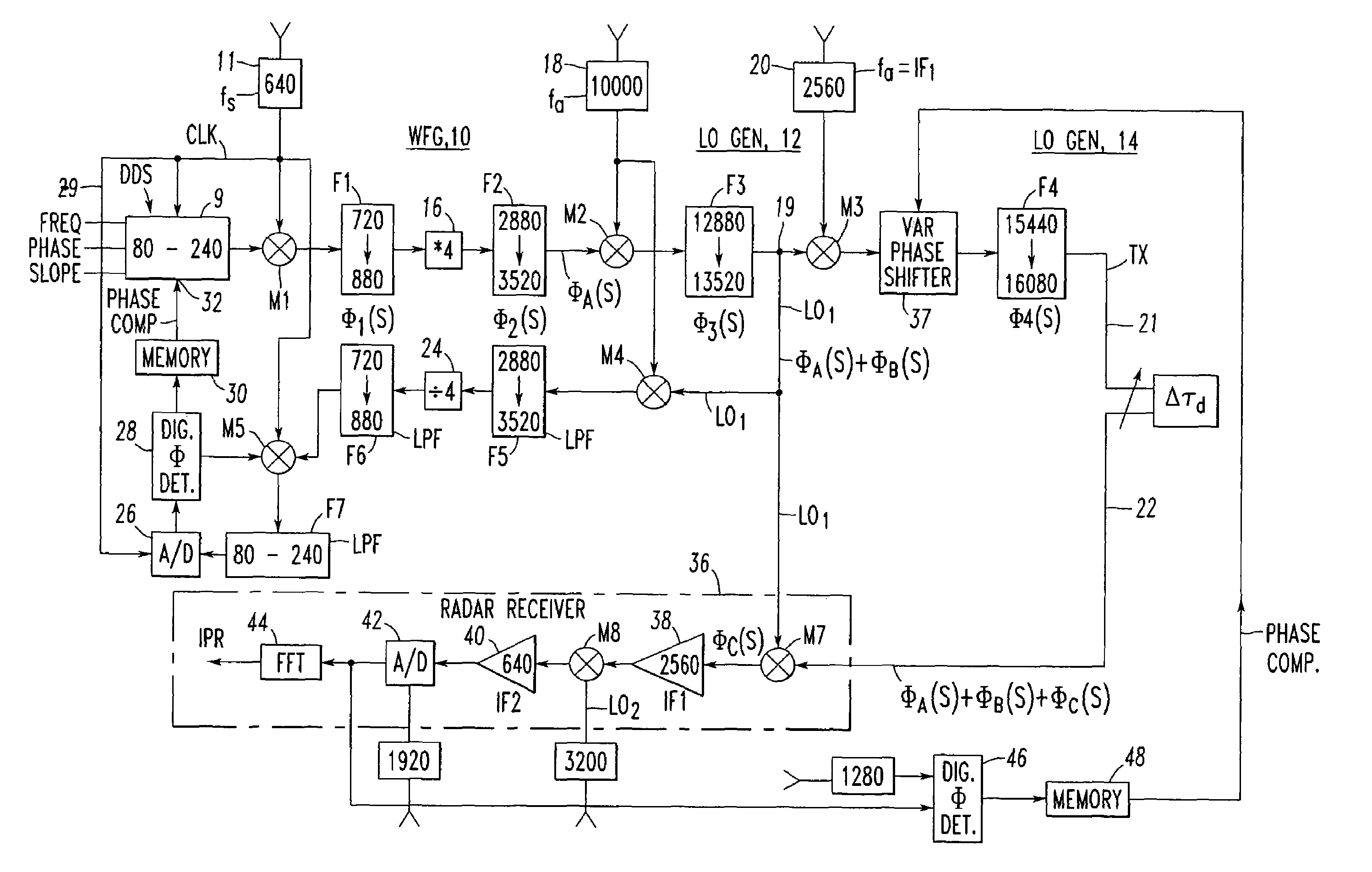
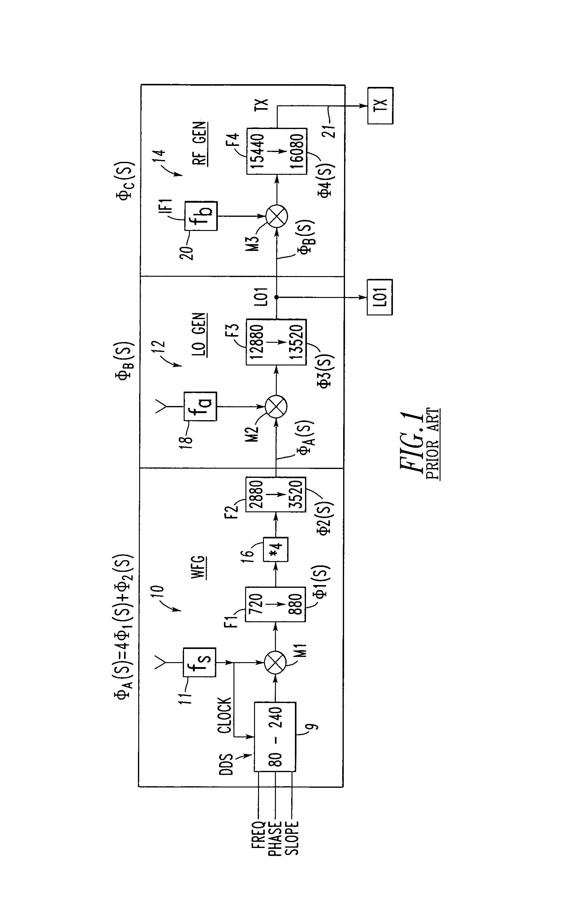
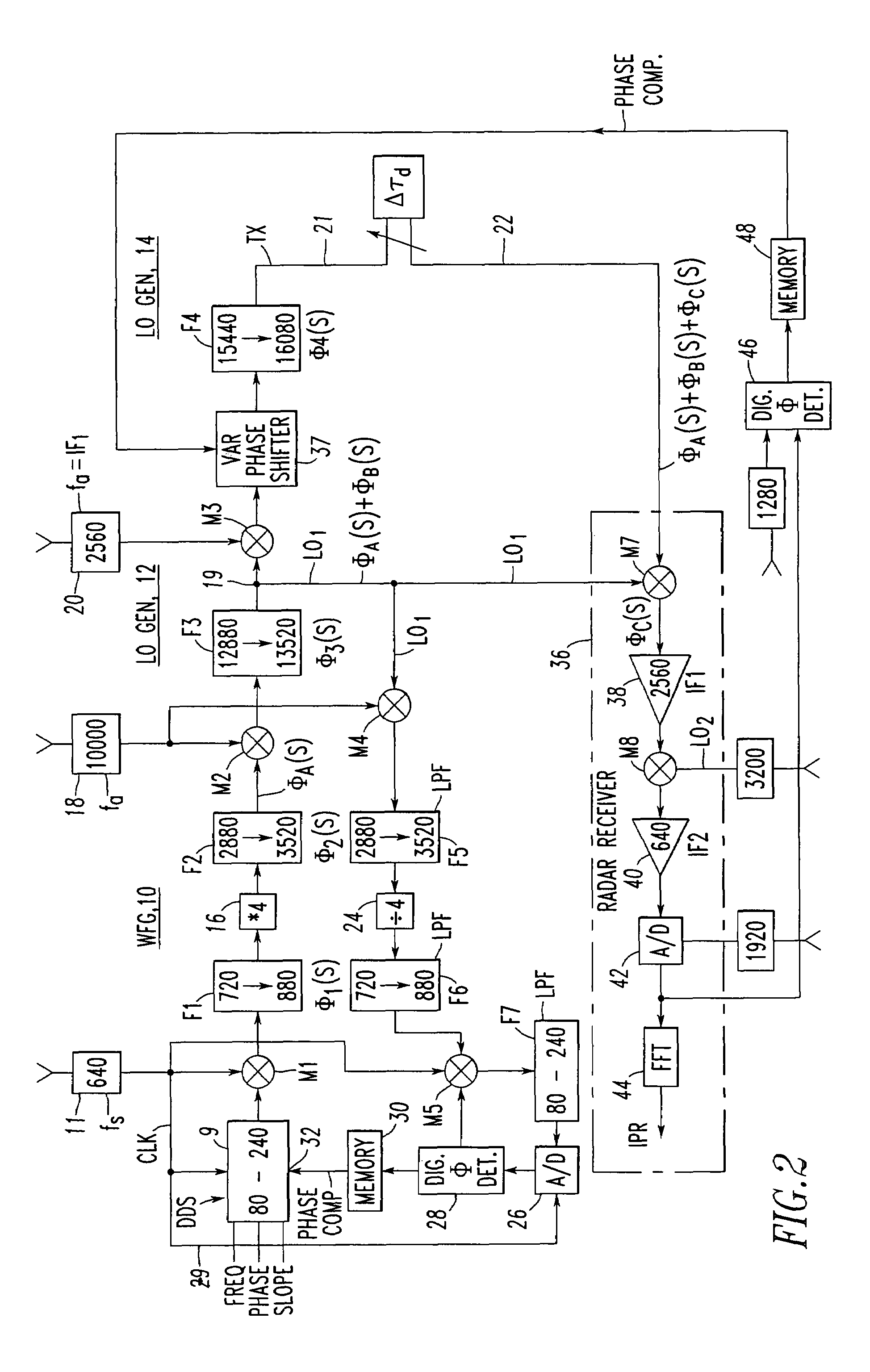
[0038]Referring now to the drawings wherein like reference numerals refer to like circuit elements throughout, and having discussed the prior art in FIG. 1 and FIG. 2 as it relates to including the elements of FIG. 1, FIG. 2 also discloses the broad concept of the subject invention where separate phase compensations are provided for both the receiver LO1 signal and the transmitter signal TX.

[0039]Referring again to FIG. 2, phase compensation in the waveform generator (WFG) 10 is achieved by down converting the LO1 signal. This is achieved by feeding LO1 at circuit node 19 including the phase perturbations ØA(S)+ØB(S) to a signal mixer M4 which also receives frequency fa. The difference signal is applied to a (228-3520 MHz) lowpass filter F5 which is then divided in frequency by a factor of 4 in a frequency divider 24. The output of the frequency divider 24 is next fed to a (720-880 MHz) lowpass filter F6, where it is then fed to another mixer M5 along with a 640 MHz fs signal via si...


PUM


Abstract

Phase compensation for the phase non-linearities introduced by the filters, amplifiers, and other microwave devices included in waveform generators in a radar system is achieved by first measuring the phase errors over a predetermined frequency range which are then fed to a pair of digital random access memories (RAMs), whereupon phase predistortion commands for both the local oscillator signal used to generate the RF transmit signal and the phase non-linearity in the RF transmit signal itself are called up and applied by first applying a predistortion phase shift to the local oscillator signal when it is being generated and secondly by applying a second predistortion phase shift when the RF transmit signal is being generated.

Description

BACKGROUND OF THE INVENTION[0001]This invention relates generally to radar exciter architecture including a wide band digital waveform generator and more particularly to the compensation of the phase non-linearities introduced in the generation and transmission of the transmitted RF output signals.DESCRIPTION OF RELATED ART[0002]Modern radar systems, such as shown and described, for example in U.S. Pat. No. 6,081,226 entitled “Multi-Mode Radar Exciter”, issued to Stephen P. Caldwell et al. on Jun. 27, 2000, include direct digital synthesis (DDS) wide band waveform generators used in generating RF output signals having highly linear FM over a bandwidth which is directly related to the DDS clock frequency. Typically, the maximum DDS frequency output is 0.4×f, where f is the DDS clock frequency. Accordingly, for a DDS clock frequency equal to 640 Mhz, the typical FM output range would be 80 Mhz to 240 Mhz, resulting in an FM bandwidth of 160 Mhz. This is shown, for example, in FIG. 1 w...

Claims


Application Information

Patent Timeline
IPC IPC(8): G01S7/40
CPCG01S7/4008
Inventor WATKINS, GRANT H.CALDWELL, STEPHEN P.
Owner NORTHROP GRUMMAN SYST CORP
Why Eureka
Try Eureka