
Automatic problem isolation for multi-layer network failures

a multi-layer network and problem isolation technology, applied in the field of computer network problem detection, can solve the problems of consuming valuable avoiding the need for software that typically resides on, and achieve the effect of valuing the processing time of network components

Active Publication Date: 2009-08-04
ATLASSIAN US INC
View PDF10 Cites 18 Cited by
  • Summary
  • Abstract
  • Description
  • Claims
  • Application Information

AI Technical Summary

Benefits of technology

[0006]A method and apparatus includes automatically correlating indicators already generated by network components to detect and isolate failures that are caused by or related to network components operating on different layers of the OSI model. Failures that persist for longer than a specified time window are automatically detected and correlated with one another based on a topology table. The method uses indicators already generated by the network components, obviating the need for software that typically resides on and consumes valuable processing time of network components.

Problems solved by technology

The method uses indicators already generated by the network components, obviating the need for software that typically resides on and consumes valuable processing time of network components.

Method used


Image

  • Automatic problem isolation for multi-layer network failures
  • Automatic problem isolation for multi-layer network failures
  • Automatic problem isolation for multi-layer network failures

Examples


Embodiment Construction

[0015]A method and apparatus includes automatically correlating indicators already generated by network components to detect and isolate failures that are caused by or related to network components operating on different layers of the OSI model. Failure indicators that persist for longer than a specified time window are automatically detected and correlated with one another based on a topology table. The method uses indicators already generated by the network components, obviating the need for software that typically resides on and consumes valuable processing time of network components.

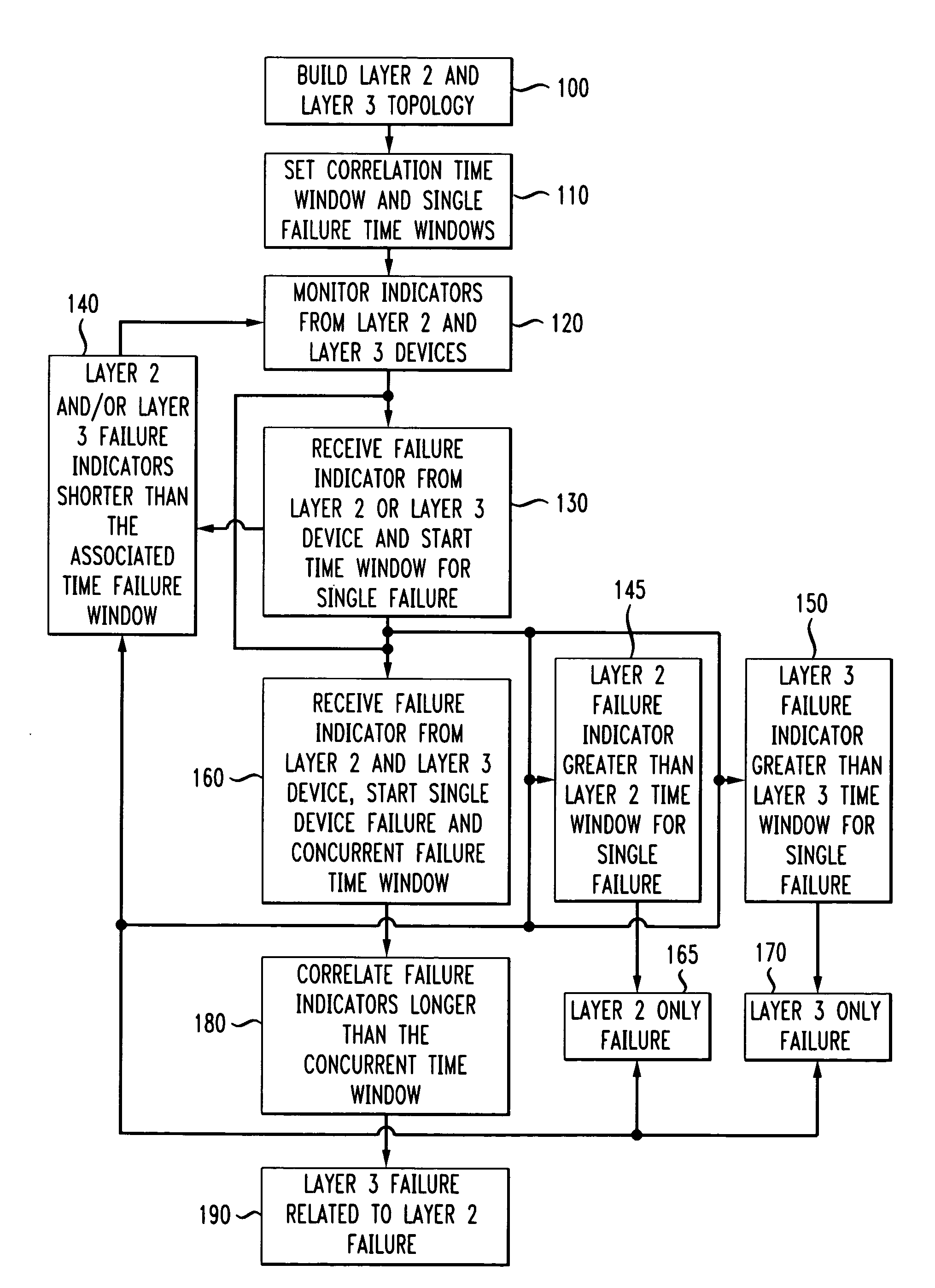
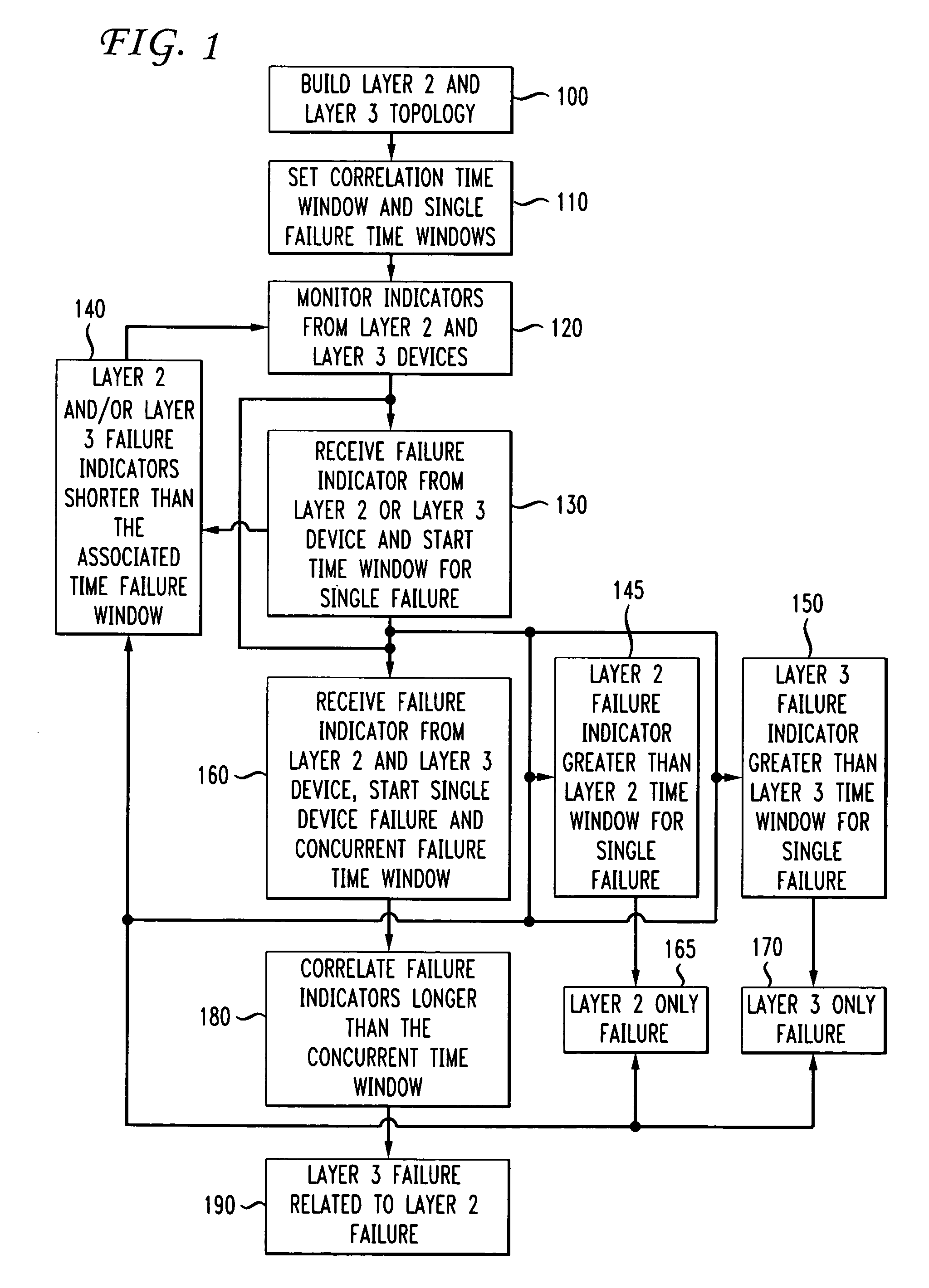
[0016]FIG. 1 is a flowchart that illustrates the detection and correlation of layer 2 to layer 3 failure indicators to detect a layer 3 device failure that is longer in duration than a specified correlation time window and is related to a layer 2 device failure. Although the embodiment in the flowchart uses layer 2 and layer 3 devices, the method could be applied to any two layers of the OSI model in...


PUM


Abstract

A method and apparatus includes automatically correlating indicators already generated by network components to detect and isolate failures that are caused by or related to network components operating on different layers of the open system interconnect (OSI) model. Failure indicators that persist for longer than a specified time window are automatically detected and correlated with one another based on a topology table. The method uses indicators already generated by the network components, obviating the need for software that typically resides on and consumes valuable processing time of network components.

Description

FIELD OF INVENTION[0001]The invention relates generally to computer network problem detection and, more particularly, to a method and apparatus for automatically isolating and detecting problems on different layers of a network.BACKGROUND[0002]Balancing network resources between maintenance and network functionality is key to the efficient, reliable, and cost-effective administration of a network. Network administrators often decrease network resources to minimize network costs, but this creates a tension between the use of network resources for detection and isolation of network problems and the use of network resources for network functionality. When network resources are allocated to automatic problem detection and isolation, network resources are unavoidably diverted away from the processing of network traffic, resulting in degraded network performance. If more resources are allocated to network functionality, network problems may go undetected and reactive manual trouble-shooti...

Claims


Application Information

Patent Timeline
Patent Type & Authority Patents(United States)
IPC IPC(8): H04L1/00
CPCH04L41/0659H04L41/064
Inventor BAJPAY, PARITOSHBEKAMPIS, CAROLYNESLAMBOLCHI, HOSSEINLI, WEN-JUILU, DAVIDMCCANUEL, JOHN
Owner ATLASSIAN US INC
Learn More