

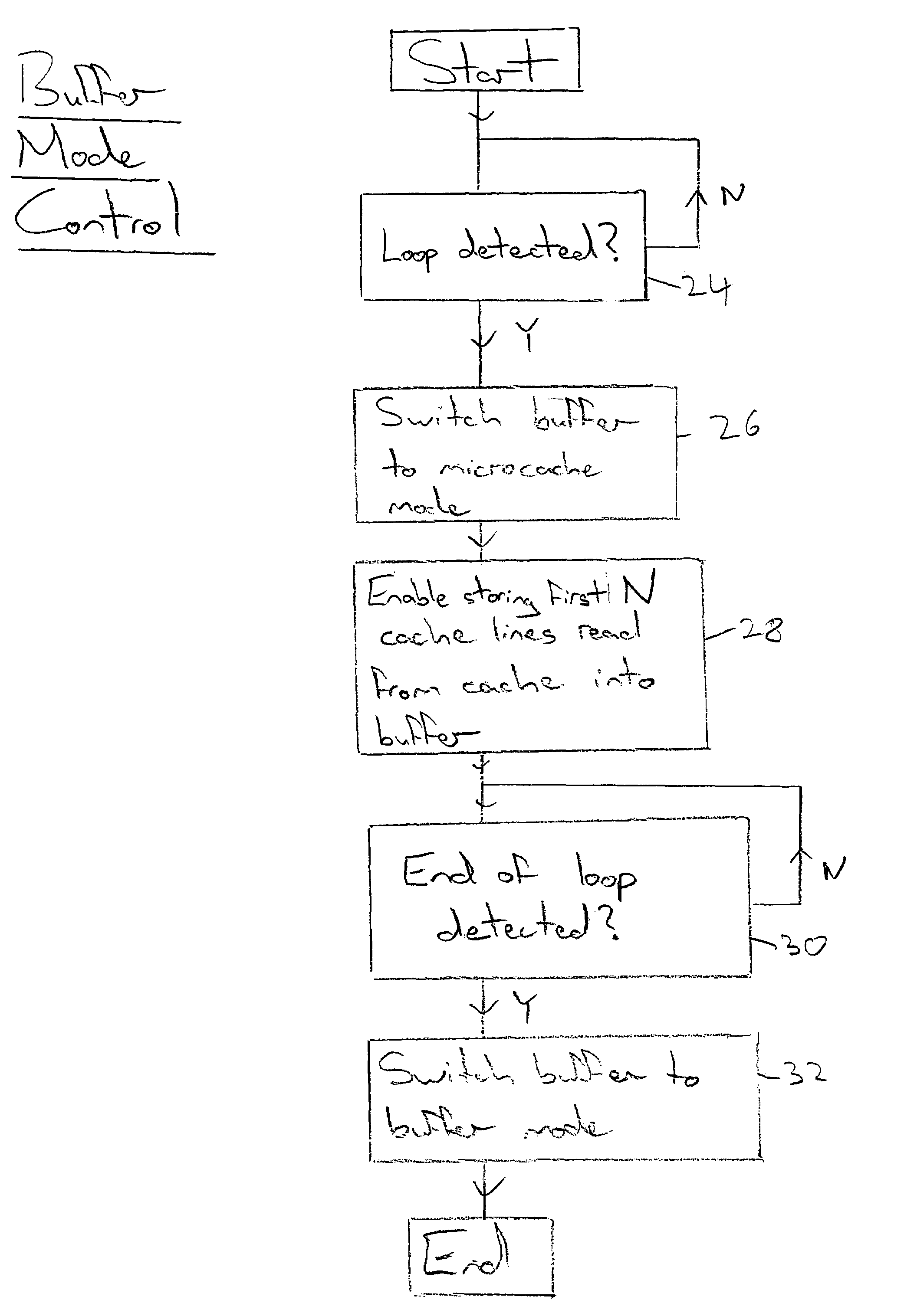
Reusing a buffer memory as a microcache for program instructions of a detected program loop
a technology of program instructions and buffer memory, applied in the field of data processing systems, to achieve the effect of low overhead, simple operation, and low overhead
- Summary
- Abstract
- Description
- Claims
- Application Information
AI Technical Summary
Benefits of technology
Problems solved by technology
Method used
Image

Examples
Embodiment Construction
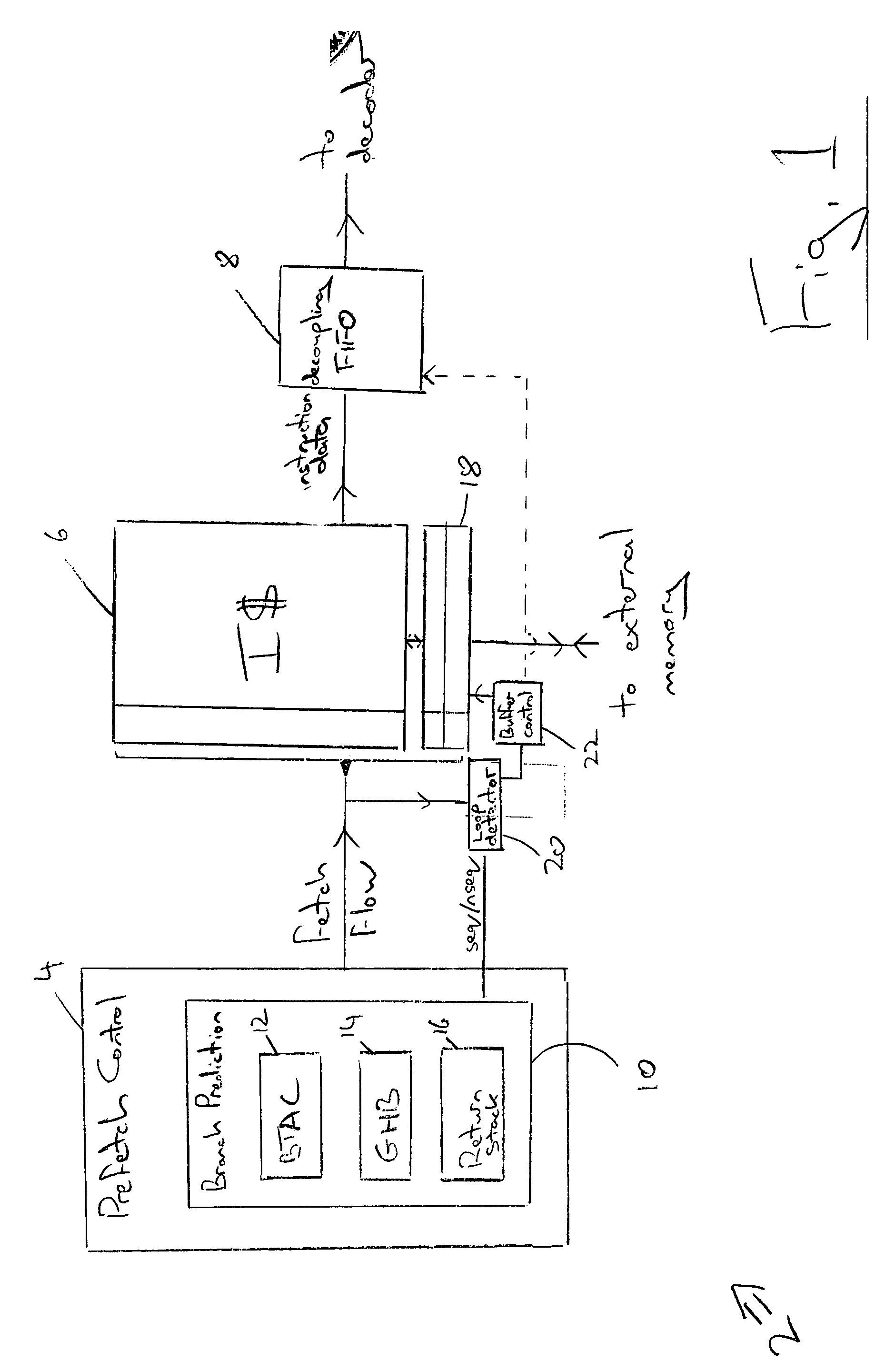
[0041]FIG. 1 illustrates a prefetch unit 2 which forms part of a data processing apparatus such as programmable microprocessor. It will be appreciated that such a prefetch unit 2 typically forms a part of an instruction pipeline within a data processing system and the data processing system will include many further circuit elements. These other circuit elements are not related to the present technique and for the sake of clarity are not illustrated in FIG. 1.
[0042]The prefetch unit 2 includes prefetch control circuitry 4, an instruction cache 6 and a decoupling buffer FIFO memory 8. The prefetch control unit 4 includes a branch predictor 10, which in turn includes a branch target address cache 12, a global history buffer 14 and a return address stack memory 16. It will be appreciated that the branch prediction mechanism 10 can include other combinations of elements as many different forms of branch prediction are known and suited to differing circumstances.
[0043]A linefill / prefetch...
PUM
 Abstract
Description
Claims
Application Information