Reactor

a technology of reactor and flow channel, which is applied in the direction of liquid-gas reaction of thin-film type, gas-gas reaction process, physical/chemical process catalyst, etc., can solve the problems of reaction device deformation or breakage, insufficient attempt, complex assembly, etc., and achieve the effect of improving the rigidity of the reaction device and increasing the length of the flow channel

Inactive Publication Date: 2009-08-11
CASIO COMPUTER CO LTD
View PDF16 Cites 3 Cited by
  • Summary
  • Abstract
  • Description
  • Claims
  • Application Information

AI Technical Summary

Benefits of technology

[0012]The present invention is directed to a reactor comprising a reaction device to which a reactant is supplied to cause reaction of the reactant, and has an advantage capable of facilitating assembling of the reaction device in which a flow channel through which the reactant flows is formed inside of the reactor, the flow channel is wobbled, thereby increasing a length of the flow channel; and capable of improving the rigidity of the reaction device, thereby causing the reaction device to be hardly deformed by a stress.

Problems solved by technology

Although a hydrogen simplex can be exemplified as a fuel for use in a fuel cell, there is a problem in handling such a hydrogen simplex due to the fact that hydrogen is gaseous at a normal temperature and under a normal pressure.
Because a storage amount of hydrogen per unit volume is small, however, such an attempt has been insufficient as means for storing a fuel of a power supply of a small sized electronic device such as a portable electrical device in particular.
That is, assembling becomes complicated.
As a consequence, the reaction device is deformed or broken due to reaction caused by a pressure difference.

Method used


Image

  • Reactor
  • Reactor
  • Reactor

Examples


first embodiment

[0115]Now, a first embodiment of the reactor according to the invention will be described here.

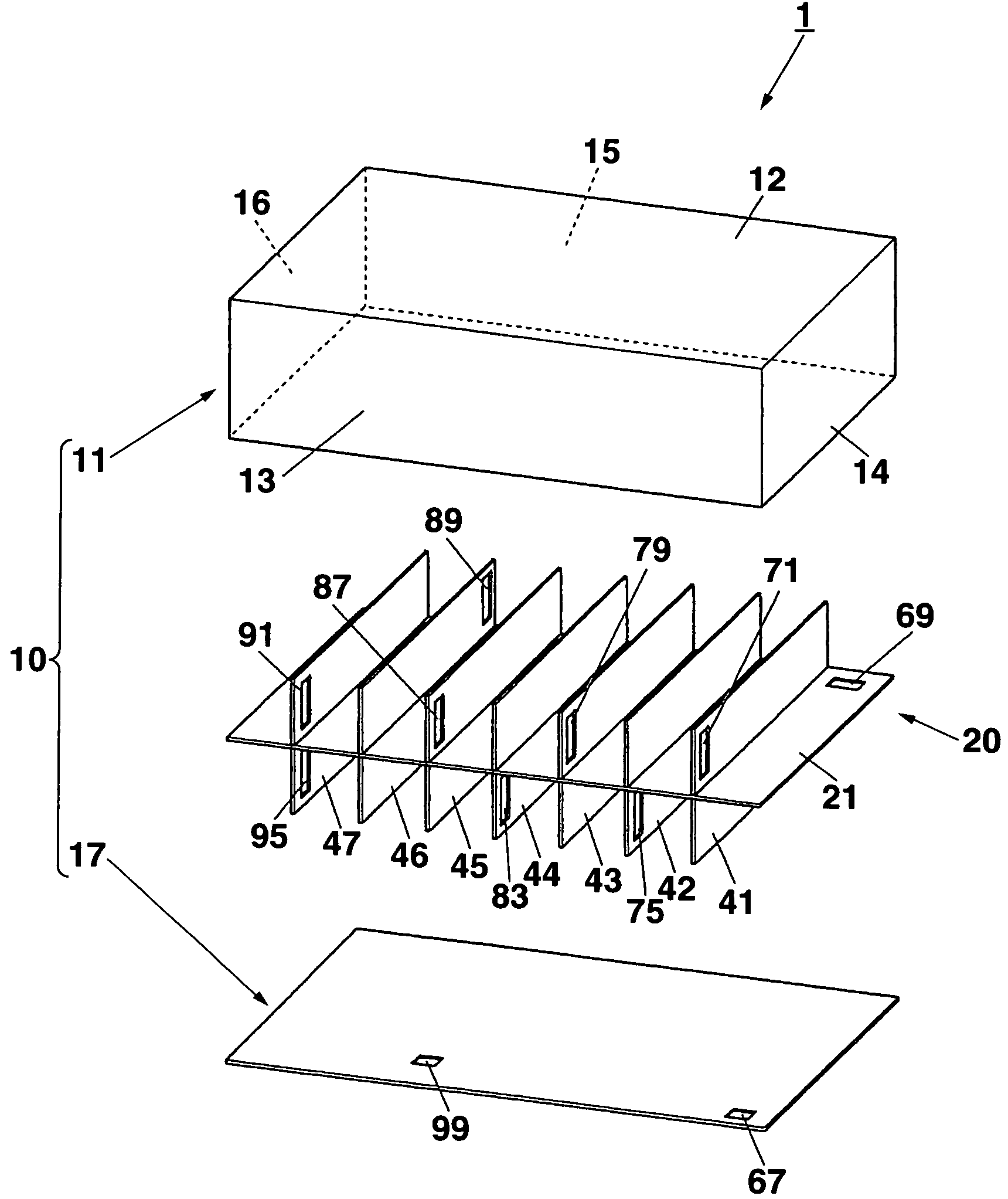
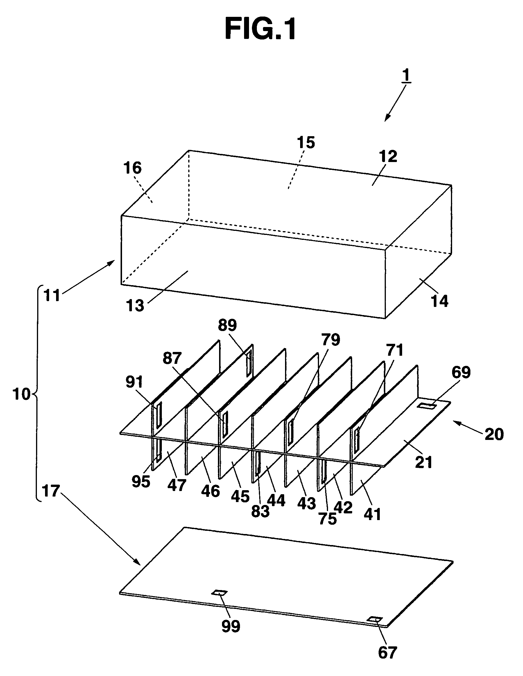
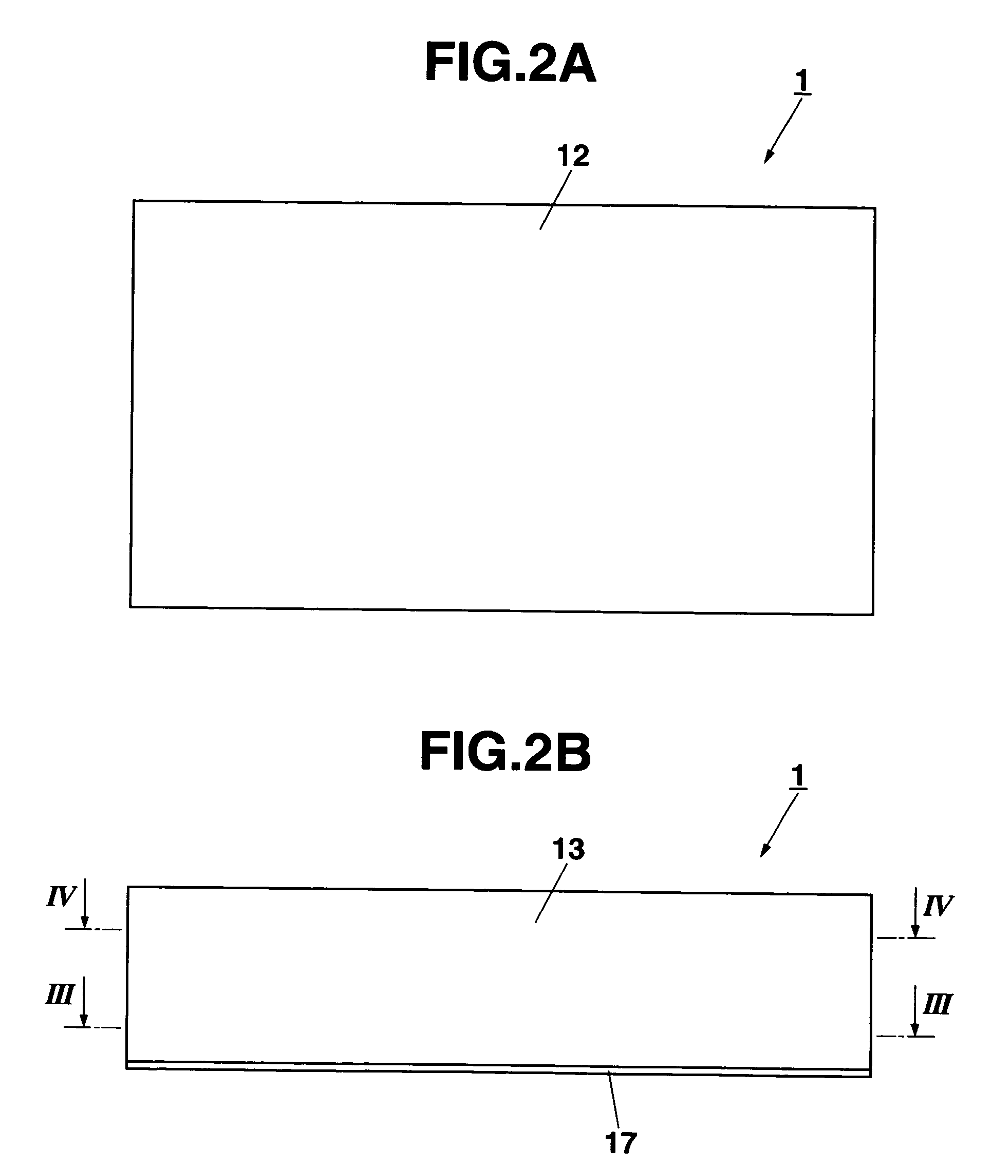
[0116]FIG. 1 is an exploded perspective view of a reaction device in the first embodiment of the reactor according to the invention as viewed from a slant upper portion. FIGS. 2A and 2B are a top view and a side view of the reaction device in the present embodiment. FIG. 3 is a cross sectional view taken along the section line III-III of FIG. 2B. FIG. 4 is a cross sectional view taken along the section line IV-IV of FIG. 2B.

[0117]The reaction device or reactor 1, as shown in FIG. 1, has a reaction vessel 10 and a partition member 20 housed in the reaction vessel 10. The reaction vessel 10 is composed of a box type member 11 and a bottom plate 17. The box type member 11 has: a rectangular top plate 12; a pair of side plates 13 and 15 connected in a state that they communicate with two opposite edges of four edges of the top plate 12 at right angle to the top plate 12; and a pair of side pla...

second embodiment

[0147]Now, a second embodiment of the reactor according to the present invention will be described here.

[0148]FIG. 9 is a side view of a microreactor module in the second embodiment of the reactor according to the invention. FIG. 10 is a schematic side view of the microreactor module 600 in this embodiment separated in terms of functions.

[0149]The microreactor module 600 is incorporated in, for example, an electronic device such as a notebook personal computer, a PDA, an electronic notebook, a digital camera, a portable cellular phone, a wristwatch, a resistor, or a projector, and produces a hydrogen gas for use in a fuel cell.

[0150]As shown in FIGS. 9 and 10, the microreactor module 600 comprises: a supply / discharge unit 602 that supplies a resistance or discharges a product; a high-temperature reaction unit 604 (first reaction unit) set at a comparatively high temperature to cause a reforming reaction; a low-temperature reaction unit 606 (second reaction unit) set at a temperature...

third embodiment

[0223]Now, a third embodiment of the reactor according to the present invention will be described here.

[0224]FIG. 20 is an exploded perspective view of a reaction device 400 in the third embodiment of the reactor according to the invention as viewed in a slant lower portion. FIGS. 21A and 21B are a top view and a lower view of the reaction device in the present embodiment. FIG. 22 is a cross sectional view taken along the section line III-III of FIG. 21B. FIG. 23 is a cross sectional view taken along the section line IV-IV of FIG. 21A.

[0225]As shown in the figures, the reactor 400 comprises a box type member 410 that opens at the bottom face; a partition plate (third partition plate: partition member) 420 housed in the box type member 410; and a bottom plate 430 that closes the lower side opening of the box type member 410.

[0226]The box type member 410, the partition plate 420, and the bottom plate 430 may be made of a planar metal material such as a stainless steel, may be made of ...


PUM

PropertyMeasurementUnit
temperatureaaaaaaaaaa

Abstract

A reactor supplied with a reactant to cause reaction of the reactant includes a reaction device which has a hollow box type member having a top plate and a bottom plate opposed to each other and side plates connected to an edge of the top plate and an edge of the bottom plate. A partition member is housed in the box type member, the partition member coming into contact with at least internal faces of the side plates of the box type member and partitioning a space in the box type member into a plurality of reaction chambers to which the reactant is to be supplied. A penetrating region is provided in the partition member to connect the adjacent reaction chambers to each other, the penetrating region having the reactant passed therethrough.

Description

CROSS-REFERENCE TO RELATED APPLICATIONS[0001]This application is based upon and claims the benefit of priority from prior Japanese Patent Applications No. 2005-284493, filed Sep. 29, 2005; No. 2005-284582, filed Sep. 29, 2005; No. 2005-284604, filed Sep. 29, 2005; and No. 2005-284700, filed Sep. 29, 2005, the entire contents of all of which are incorporated herein by reference.BACKGROUND OF THE INVENTION[0002]1. Field of the Invention[0003]The present invention relates to a reactor to which a reactant is supplied, thereby causing reaction of the reactant.[0004]2. Description of the Related Art[0005]In recent years, a development has been underway to mount a fuel cell as a clean power supply with its high efficiency of energy conversion in automobiles or portable devices. The fuel cell is a device that causes a fuel and oxygen that is contained in an atmospheric air to react with each other in an electrochemical manner, thereby directly extracting electrical energy from chemical ener...

Claims


Application Information

Patent Timeline
Patent Type & Authority Patents(United States)
IPC IPC(8): B01J7/02B01J10/00B01J8/02H01M8/18
CPCB01J19/0093C01B3/323B01J19/249Y02E60/324B01J2219/00783B01J2219/00822B01J2219/00824B01J2219/00831B01J2219/00833B01J2219/00835B01J2219/00867B01J2219/00959B01J2219/00961B01J2219/2453B01J2219/2458B01J2219/2466B01J2219/2467B01J2219/247B01J2219/2479B01J2219/2485B01J2219/2486B01J2219/2487B01J2219/2488B01J2219/249B01J2219/2496C01B2203/0233C01B2203/044C01B2203/047C01B2203/066C01B2203/0811C01B2203/0822C01B2203/085C01B2203/1035C01B2203/1064C01B2203/1076C01B2203/1082C01B2203/1223Y02P20/10C01B3/00C01B3/24C01B3/26C01B3/38Y02E60/32
Inventor MIYAMOTO, NAOTOMOSAITO, KAORUYAMAMOTO, TADAO
Owner CASIO COMPUTER CO LTD
Why Eureka
Try Eureka