SET/RESET latch circuit, Schmitt trigger circuit, and MOBILE based D-type flip flop circuit and frequency divider circuit thereof

a technology of latch circuit and trigger circuit, which is applied in the direction of logic circuits using specific components, pulse generators, pulse techniques, etc., can solve the problems of difficult application of rz-mode mobile circuit to very high-speed digital circuits, and achieve high-efficiency low-power characteristics, easy use, and improved operation speed of set/reset latch circuits

Inactive Publication Date: 2009-08-11
KOREA ADVANCED INST OF SCI & TECH
View PDF12 Cites 14 Cited by
  • Summary
  • Abstract
  • Description
  • Claims
  • Application Information

AI Technical Summary

Benefits of technology

[0013]As described in the above, SET / RESET latch circuit, Schmitt trigger circuit, MOBILE based D-type flip flop circuit and frequency divider circuit using SET / RESET latch circuit and Schmitt trigger circuit in accordance with the present invention have the following advantageous effects.
[0014]1) Operating speed of SET / RESET latch circuit is improved by using CML-type transistors, and the SET / RESET latch circuit also provides differential outputs so that it can be easily used for the conventional very high-speed digital circuits.
[0015]2) A Schmitt trigger circuit with threshold voltages VTH and VTL is implemented by using SET port and RESET port of SET / RESET latch as VIN and VREF, respectively.
[0016]3) Moreover, compared to the conventional SCFL or ECL-type D-type flip flop circuit, NRZ-mode D-type flip flop circuit in the present invention requires a small number of devices. Since feedback loop is not required, NRZ mode D-type flip flop circuit with highly efficient low-power characteristic as well as very high operating speed can be implemented.
[0017]4) Moreover, a 2:1 static frequency divider can be implemented by feeding the output of NRZ mode D-type flip flop circuit (proposed in the present invention) back to the input port (i.e., feedback output to input).

Problems solved by technology

In fact, since Non-Return-to-Zero(NRZ)-mode signal system is utilized for increasing operation speed of system in very high speed optical communication system, it has difficulties in applying RZ-mode MOBILE circuit to very high speed digital circuits.

Method used


Image

  • SET/RESET latch circuit, Schmitt trigger circuit, and MOBILE based D-type flip flop circuit and frequency divider circuit thereof
  • SET/RESET latch circuit, Schmitt trigger circuit, and MOBILE based D-type flip flop circuit and frequency divider circuit thereof
  • SET/RESET latch circuit, Schmitt trigger circuit, and MOBILE based D-type flip flop circuit and frequency divider circuit thereof

Examples


Embodiment Construction

]

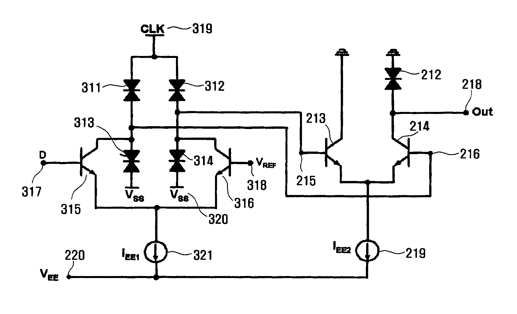
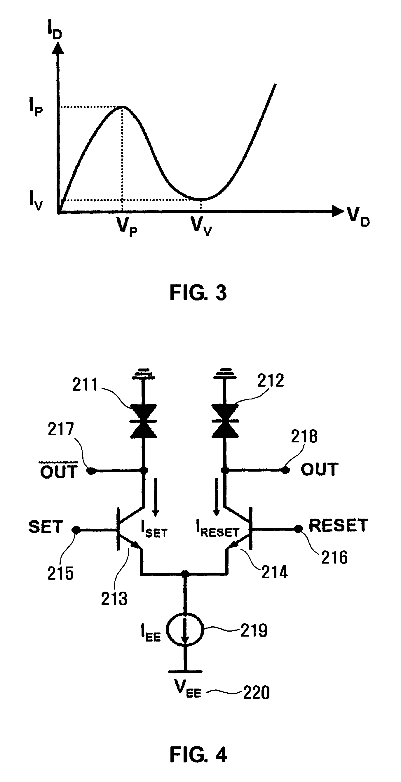
[0091]The invention is directed to present SET / RESET latch circuit, which is characterized by including a transistor 1 and 2 in which each emitter of said transistors is commonly connected to a current source, and a negative differential resistance diode which is connected to a collector of only one transistor of said transistor 1 and 2; and additionally performing to be the relationship of IPEEP(where, IP: the peak current of a negative differential resistance diode, IEE: the current of the current source connected in serial to the common node of emitters of a transistor 1 and 2); and

[0092]thereby providing a single Non-Return-to-Zero mode output in case that Return-to-Zero mode SET and RESET voltages are respectively supplied on is the base ports of said transistor 1 and 2.

[0093]Likewise, the invention is directed to present SET / RESET latch circuit, which is characterized by including a transistor 1 and 2 in which each emitter of said transistors is commonly connected to a curren...


PUM


Abstract

The present invention relates to a SET / RESET latch circuit a Schmitt trigger circuit, and a MOBILE based D-type flip flop circuit and frequency divider circuit using the SET / RESET latch circuit and Schmitt trigger circuit. The SET / RESET latch circuit is configured with CML-type transistors and negative differential resistance diodes. The SET / RESET latch circuit can be applied to very high speed digital circuits.

Description

TECHNICAL FIELD[0001]The present invention relates to SET / RESET latch circuit, Schmitt trigger circuit, and MOBILE (MOnostable-BIstable transition Logic Element) based D-type flip flop circuit and frequency divider circuit using the SET / RESET latch circuit and Schmitt trigger circuit.[0002]With a view to increasing the operating speed and being applicable to very high speed circuits, a SET / RESET latch circuit using CML(Current Mode Logic)-type 3-port transistors and negative differential resistance diodes, and its application circuits are presented.[0003]Operating speed of SET / RESET latch circuit is improved by using CML-type transistors, and the SET / RESET latch circuit also provides differential outputs so that it can be easily used for conventional very high-speed digital circuits such as ECL(Emitter-Coupled Logic) and SCFL(Source Coupled FET Logic). A Schmitt trigger circuit with threshold voltages VTH and VTL is implemented by using SET port and RESET port of SET / RESET latch as ...

Claims


Application Information

Patent Timeline
Patent Type & Authority Patents(United States)
IPC IPC(8): H03K3/315
CPCH03K3/2885H03K3/2897H03K5/00006H03K3/315H03K17/58H03K3/023H03K17/22
Inventor YANG, KYOUNG-HOONKIM, TAE-HOJEONG, YONGSIK
Owner KOREA ADVANCED INST OF SCI & TECH
Why Eureka
Try Eureka