
Quadrature voltage controlled oscillator with automated phase control

a voltage control and phase control technology, applied in pulse generators, pulse manipulation, pulse techniques, etc., can solve the problems of affecting the performance of the receiver, and the in-phase components of the voltage control oscillator may not have an ideal quadrature relationship with the quadrature-phase components

Inactive Publication Date: 2009-08-11
SAMSUNG ELECTRONICS CO LTD
View PDF4 Cites 2 Cited by
  • Summary
  • Abstract
  • Description
  • Claims
  • Application Information

AI Technical Summary

Benefits of technology

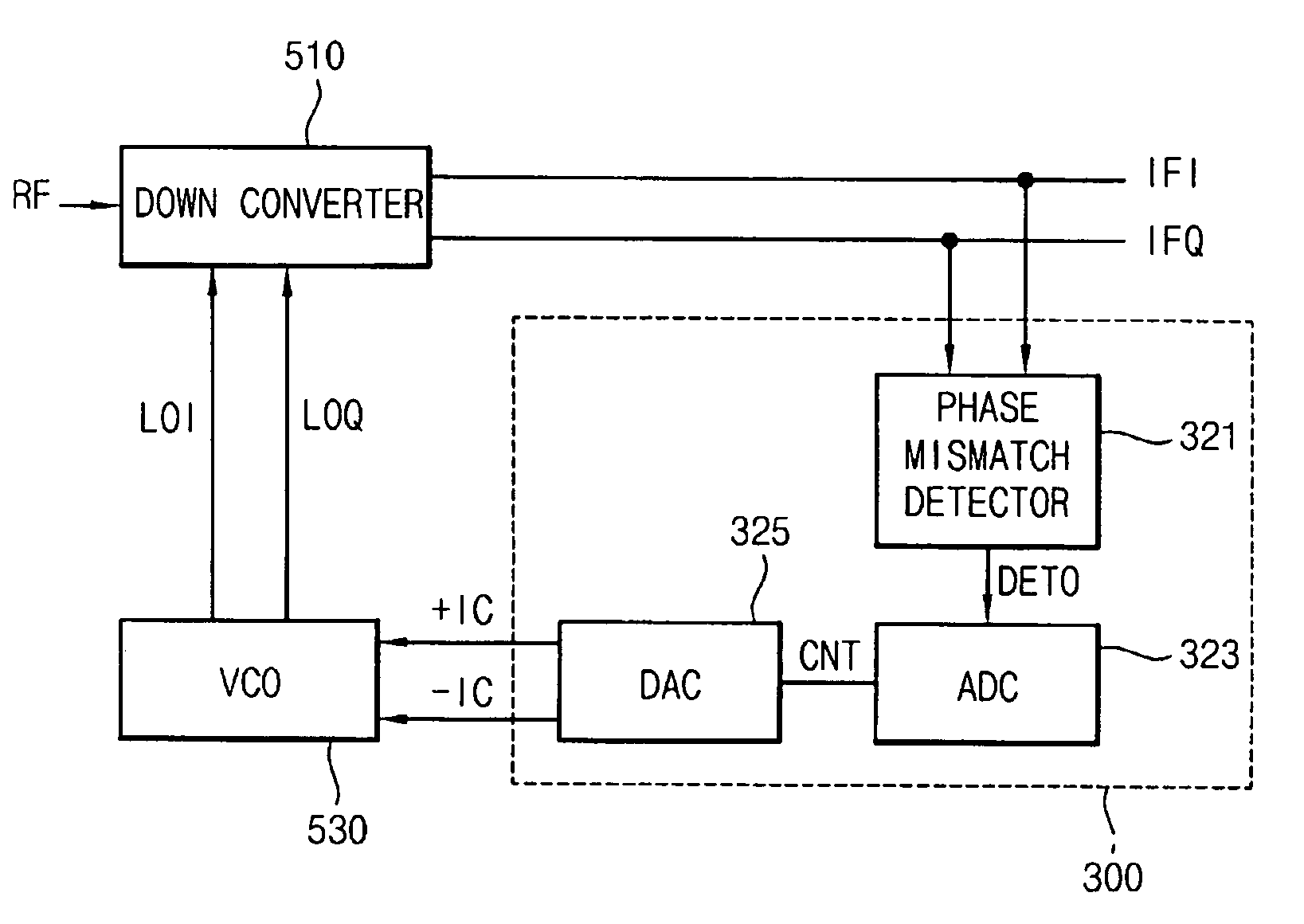
The present invention relates to a technology for controlling the phase relationship between oscillation signals in a wireless receiver. The invention includes a quadrature voltage controlled oscillator that generates in-phase and quadrature-phase oscillation signals, which are used to mix with an RF signal to generate the output signals. A compensation circuit adjusts the biasing in the oscillation circuits based on the phase relationship between the output signals to set a phase difference of about 90 degrees. This allows for automatic control of the phase relationship between the oscillation signals. The invention can be used in wireless receivers to improve signal quality and reliability.

Problems solved by technology

The down-converted image signal may interfere with the desired down-converted radio signal and degrade the receiver's performance.
However, integration of such extra filters on to the same circuit as the receiver in FIG. 1 is difficult.
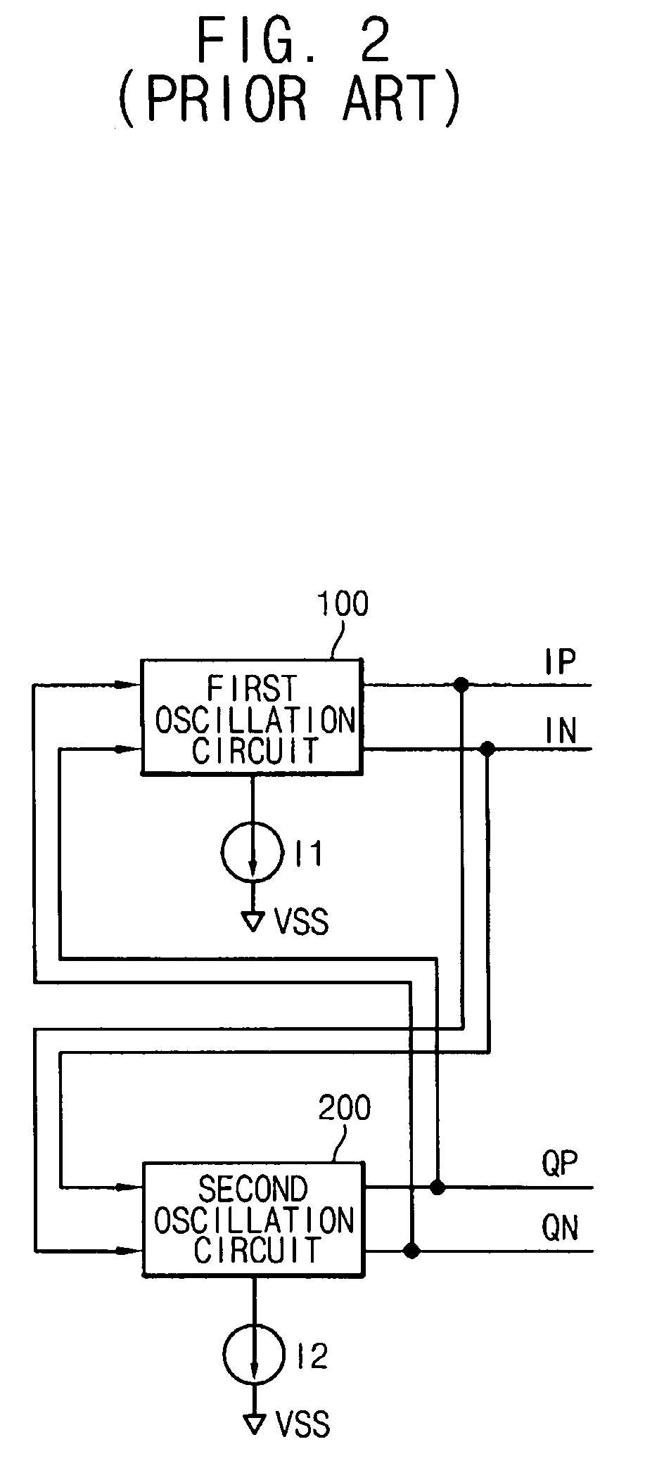
However, the in-phase components of the voltage controlled oscillator may not have an ideal quadrature relationship with the quadrature-phase components.
Such an error in the phase difference is mainly due to device mismatch in the voltage controlled oscillator.
However, such a passive filter within the receiver complicates the design and increases the chip size of the receiver.
In U.S. Pat. No. 6,462,626, an amplifying ratio of the amplifier in the quadrature oscillator device is controlled for a precise quadrature relationship between an in-phase signal component I and a quadrature phase signal component Q. However, such a gain adjustment may be manual after measurement of the in-phase and quadrature signal components I and Q. Such manual adjustment may be time-consuming and prone to error.

Method used


Image

  • Quadrature voltage controlled oscillator with automated phase control
  • Quadrature voltage controlled oscillator with automated phase control
  • Quadrature voltage controlled oscillator with automated phase control

Examples


Embodiment Construction

[0033]FIG. 3 shows a block diagram of a quadrature voltage controlled oscillator according to an exemplary embodiment of the present invention. Referring to FIG. 3, the quadrature voltage controlled oscillator includes a phase compensation circuit 300, a first oscillation circuit 100, a first current source 410, a second oscillation circuit 200, and a second current source 420.

[0034]The phase compensation circuit 300 receives an in-phase output signal IFI and a quadrature-phase output signal IFQ to detect a level of deviation from a desired phase difference (such as 90° for example) between the in-phase and quadrature-phase output signals IFI and IFQ. Additionally, the phase compensation circuit 300 generates first and second compensation signals −IC and +IC based on the phase deviation for complementarily controlling first and second bias currents I1 and I2.

[0035]The first oscillation circuit 100 receives quadrature-phase oscillation signals QP and QN from the second oscillation ci...


PUM


Abstract

A quadrature voltage controlled oscillator includes oscillation circuits for generating in-phase and quadrature-phase oscillation signals that are used to generate in-phase and quadrature-phase output signals. A compensation circuit adjusts biasing in the oscillation circuits depending on a phase relationship between the in-phase and quadrature-phase output signals to automatically control the phase relationship between the oscillation signals.

Description

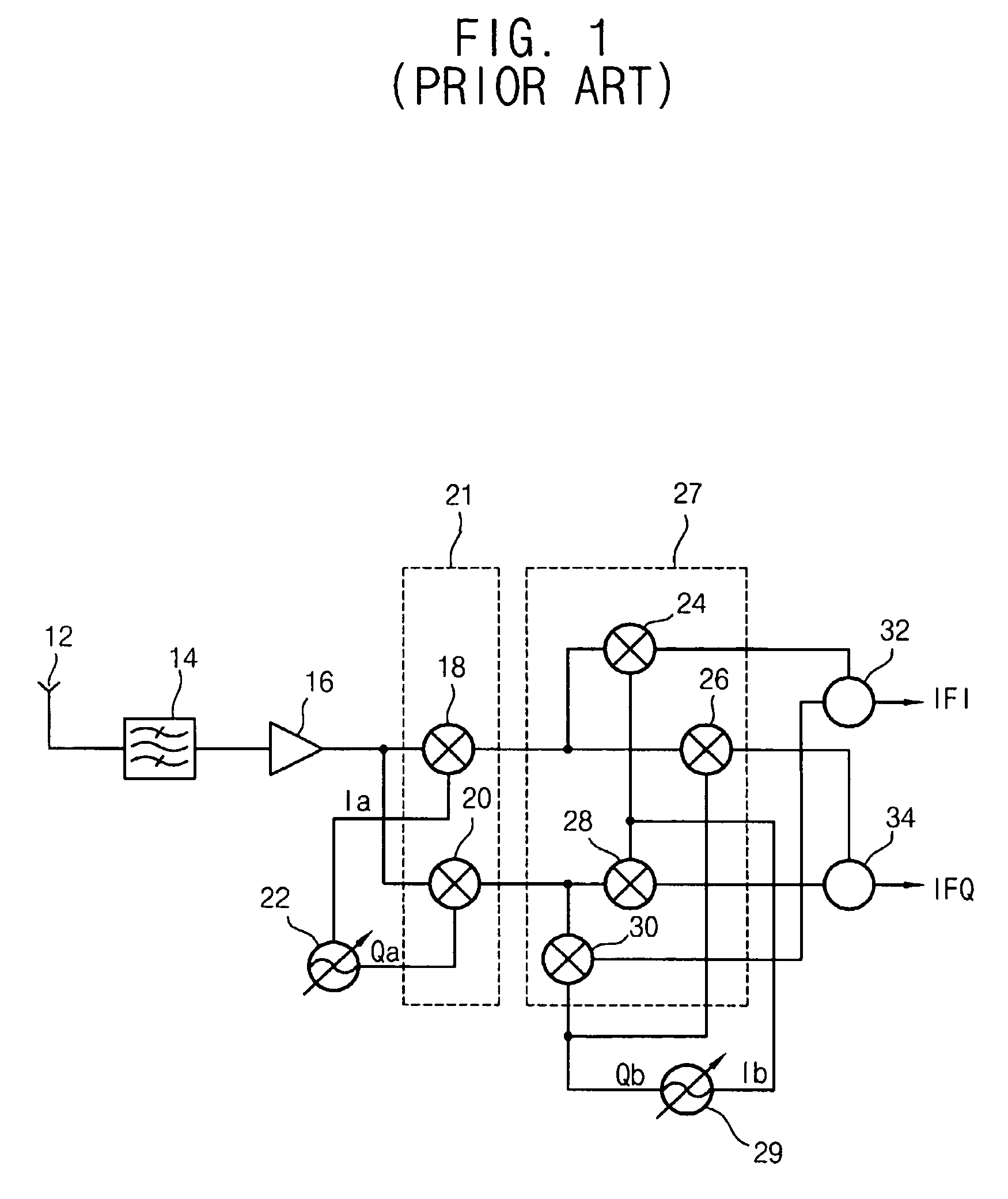
BACKGROUND OF THE INVENTION[0001]This application claims priority under 35 USC § 119 to Korean Patent Application No. 2004-44515, filed on Jun. 16, 2004, the contents of which are herein incorporated by reference in their entirety for all purposes.[0002]1. Field of the Invention[0003]The present invention relates generally to wireless receivers, and in particular to a quadrature voltage controlled oscillator used within a wireless receiver for generating oscillation signals with automated phase control.[0004]2. Description of the Related Art[0005]FIG. 1 shows a conventional wireless receiver as disclosed in U.S. Pat. No. 6,462,626 entitled “Quadrature Output Oscillator Device”. Referring to FIG. 1, the conventional receiver includes an antenna 12 for receiving an RF (radio frequency) signal. The RF signal is filtered by a filter 14 and amplified by an amplifier 16.[0006]The filtered and amplified RF signal is then applied to a first mixer 18 and a second mixer 20 of a first mixing s...

Claims


Application Information

Patent Timeline
Patent Type & Authority Patents(United States)
IPC IPC(8): H03B27/00H03B5/12H03D3/00H03D3/24H04L27/06
CPCH03B27/00H03D3/009H03B5/1271H03B5/1215H03B5/1228H03B2200/0078
Inventor KIM, YOUNG-JIN
Owner SAMSUNG ELECTRONICS CO LTD
Learn More