Multi-plane optical apparatus

a multi-plane optical apparatus and optical light technology, applied in the field of optical light transmission, can solve the problems of inability to view sharp images at a closer distance, heavy crt display, bulky and not easily miniaturized, etc., and achieve the effect of efficient transmission of chromatic ligh

Inactive Publication Date: 2009-08-11
MIRAGE INNOVATIONS LTD
View PDF76 Cites 243 Cited by
  • Summary
  • Abstract
  • Description
  • Claims
  • Application Information

AI Technical Summary

Benefits of technology

[0018]According to one aspect of the present invention there is provided an optical apparatus for transmitting light generated by a chromatic light source, the light having a spectrum of wavelengths, the apparatus comprising a plurality of optical devices design and constructed to decompose the light into a plurality of portions respectively corresponding to different sub-spectra of the spectrum, such that each portion of the plurality of portions is efficiently transmitted within a different optical device.
[0024]According to another aspect of the present invention there is provided a system for providing an image to a user, the image being constituted by light having a spectrum of wavelengths, the system comprising: an optical apparatus which comprises a plurality of optical devices design and constructed to decompose and recompose the light, in a manner such that different portions of the light, corresponding to different sub-spectra of the spectrum, efficiently propagate within different optical devices and exit the optical apparatus into at least a first eye of the user; and an image generating device for providing the optical apparatus with the image.
[0028]According to yet another aspect of the present invention there is provided a method of transmitting light having a spectrum of wavelengths, the method comprising decomposing the light into a plurality of portions respectively corresponding to different sub-spectra of the spectrum, and efficiently transmitting each of the light within a different optical device.
[0050]The present invention successfully addresses the shortcomings of the presently known configurations by providing an apparatus, system and method for an efficient transmission of chromatic light.

Problems solved by technology

Unless a person is long-sighted, he may not be able to view a sharp image at a closer distance.
The CRT displays are heavy, bulky and not easily miniaturized.
The active matrix panel uses a transistor to control each pixel, and is more expensive.
Small size real image displays have a relatively small surface area on which to present a real image, thus have limited capability for providing sufficient information to the user.
In other words, because of the limited resolution of the human eye, the amount of details resolved from a small size real image might be insufficient.
For example, such displays have suffered from being too heavy for comfortable use, as well as too large so as to be obtrusive, distracting and even disorienting.
These defects stem from, inter alia, the incorporation of relatively large optics systems within the mounting structures, as well as physical designs which fail to adequately take into account important factors as size, shape, weight, etc.
A common problem to all types of holographic optical elements is their relatively high chromatic dispersion.
This is a major drawback in applications where the light source is not purely monochromatic.
Another drawback of some of these displays is the lack of coherence between the geometry of the image and the geometry of the holographic optical element, which causes aberrations in the image array that decrease the image quality.
New designs, which typically deal with a single holographic optical element, compensate for the geometric and chromatic aberrations by using non-spherical waves rather than simple spherical waves for recording; however, they do not overcome the chromatic dispersion problem.
Moreover, with these designs, the overall optical systems are usually every complicated and difficult to manufacture.
Furthermore, the field-of-view resulting from these designs is usually very small.
Upatnieks, however, does not teach how the display could transmit a wide field-of-view, or tackle a broad spectrum of wavelengths (for providing color images).
However, the diffractive collimating element of Friesem et al. is known to narrow spectral response, and the low chromatic sensitivity at spectral range of ±2 nm becomes an unacceptable sensitivity at ±20 nm or ±70 nm.
The resulting images of such devices therefore suffer from low quality due to non-uniform color brightness.

Method used


Image

  • Multi-plane optical apparatus
  • Multi-plane optical apparatus
  • Multi-plane optical apparatus

Examples


Embodiment Construction

[0060]The present invention is of an apparatus system, and method which can be used for transmitting chromatic light. Specifically, the present invention can be used to efficiently transmit chromatic virtual images into the eyes of the user.

[0061]Before explaining at least one embodiment of the invention in detail, it is to be understood that the invention is not limited in its application to the details of construction and the arrangement of components set forth in the following description or illustrated in the drawings. The invention is capable of other embodiments or of being practiced or carried out in various ways. Also, it is be understood that the phraseology and terminology employed herein is for the purpose of description and should not be regarded as limiting.

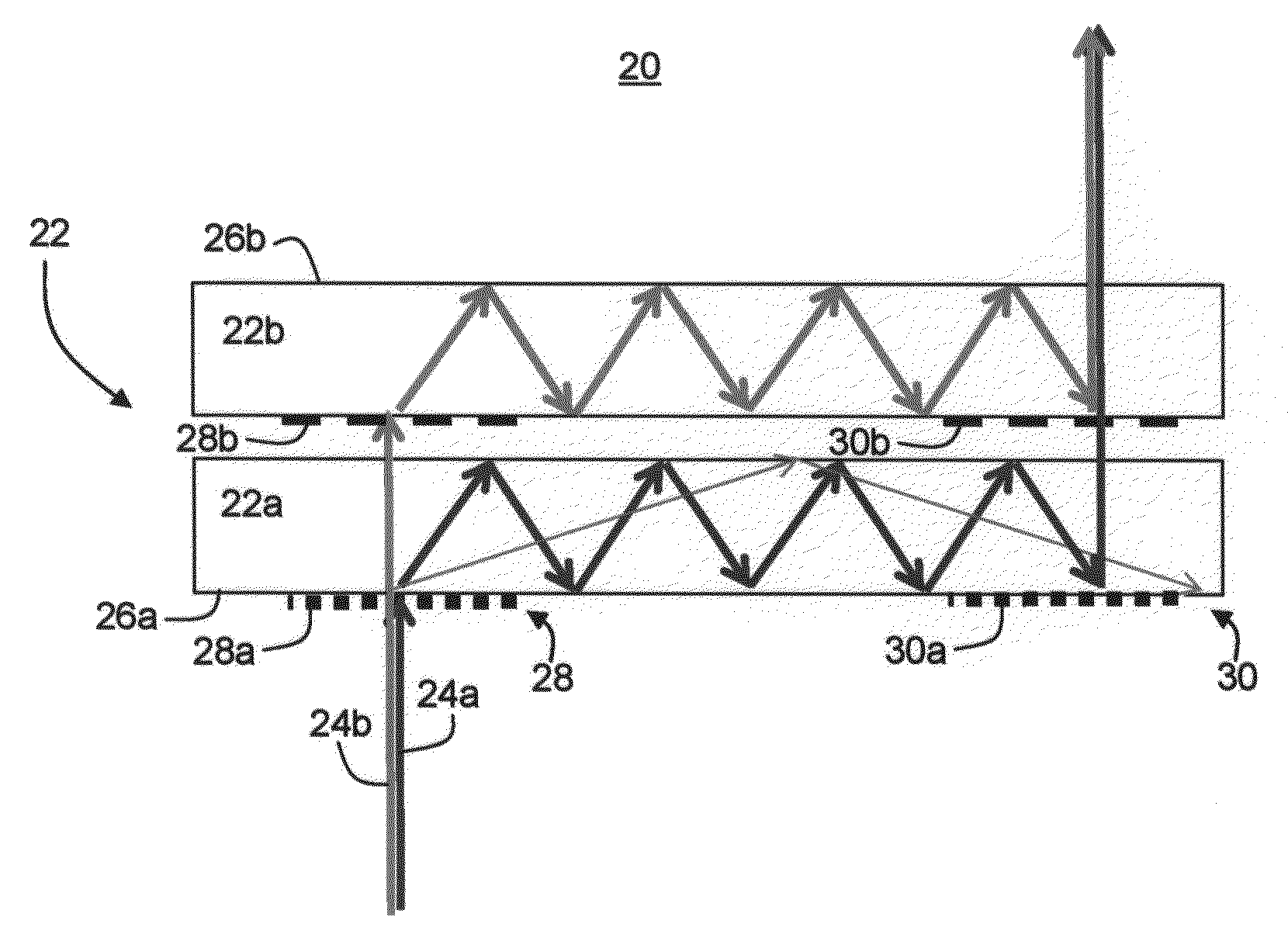
[0062]When a ray of light moving within a light-transmissive substrate and striking one of its internal surfaces at an angle α1 as measured from a normal to the surface, it can be either reflected from the surface or...


PUM


Abstract

An optical apparatus for transmitting light having a spectrum of wavelengths is disclosed. The apparatus comprises a plurality of optical devices design and constructed to decompose the light into a plurality of portions, respectively corresponding to different sub-spectra of the spectrum, such that each portion of the light is transmitted within a different optical device.

Description

[0001]This application claims the benefit of priority from U.S. Provisional Patent Application No. 60 / 667,773, filed Apr. 4, 2005.FIELD AND BACKGROUND OF THE INVENTION[0002]The present invention relates to the field of optics and, more particularly, to a method, apparatus and system for transmitting a chromatic light by decomposing the light into two or more sub-spectra thereby improving the transmission efficiency of the light.[0003]Miniaturization of electronic devices has always been a continuing objective in the field of electronics. Electronic devices are often equipped with some form of a display, which is visible to a user. As these devices reduce in size, there is an increase need for manufacturing compact displays, which are compatible with small size electronic devices. Besides having small dimensions, such displays should not sacrifice image quality, and be available at low cost. By definition the above characteristics are conflicting and many attempts have been made to p...

Claims


Application Information

Patent Timeline
Patent Type & Authority Patents(United States)
IPC IPC(8): G02B27/14G02B27/44
CPCG02B5/1814G02B6/0076G02B6/29329G02B6/2938G02B27/0172G02B27/102G02B27/1086G02B27/4211G02B27/4216G02B27/4272G02B5/1866G02B2027/0174G02B6/00G02B6/0016G02B6/0038G02B6/0043G02B2027/011G02B2027/0112G02B2027/0116G02B2027/0118G02B2027/0125G02B5/18
Inventor NIVON, UZIANIV, YEHUDA
Owner MIRAGE INNOVATIONS LTD
Why Eureka
Try Eureka